CA3140 Datasheet PDF – Operational Amplifier | Intersil

Part Number: CA3140EZ

Function: 4.5MHz, BiMOS operational amplifier with MOSFET input/bipolar output

Package: DIP 8, SOIC 8, Can 8 Pin Type

Manufacturer: Intersil

Image

CA3140 datasheet pdf

Description

The CA3140A and CA3140 are integrated circuit operational amplifiers that combine the advantages of high voltage PMOS transistors with high voltage bipolar transistors on a single monolithic chip.

Features

  • MOSFET input stage providing ultra-high input impedance
  • Very low input current of approximately 10pA at ±15V
  • Wide common-mode input voltage range extending below negative rail
  • Output voltage swing closely tracks input common-mode range
  • High voltage operation with combined PMOS and bipolar technology
  • Low power consumption suitable for portable systems

Pinout

CA3140 pinout

Typical Circuit Usage

  • Voltage follower for high-impedance signal buffering
  • Integrator and differentiator circuits in analog computation
  • Active low-pass and band-pass filter implementations
  • Comparator circuits with adjustable thresholds
  • Photodiode amplifier for light sensing applications

How to Choose This Part

  • Select when extremely high input impedance is required
  • Useful in designs where input current must be minimized
  • Appropriate for single-supply or dual-supply analog systems
  • Preferred for precision low-frequency signal processing
  • Consider alternatives if high-speed or rail-to-rail precision is critical

Applications

• Ground-Referenced Single Supply Amplifiers in Automobile and Portable Instrumentation

• Sample and Hold Amplifiers

• Long Duration Timers/Multivibrators (μseconds-Minutes-Hours)

• Photocurrent Instrumentation

• Peak Detectors

• Active Filters

• Comparators

Alternative / Equivalent Products

  • CA3130 high-speed MOSFET input operational amplifier
  • TL071 JFET input operational amplifier
  • LF351 low-noise JFET input op-amp
  • OPA134 precision audio operational amplifier
  • LM358 general-purpose dual operational amplifier

Other data sheets are available within the file: CA3140A, CA3140AE, CA3140AT, CA3140E

CA3140 Datasheet PDF Download

CA3140 download
CA3140 pdf


AD8002 Datasheet PDF – Current Feedback Amplifier

Part Number: AD8002

Function: Dual 600 MHz, 50 mW Current Feedback Amplifier

Package: DIP, SOIC 8 Pin Type

Manufacturer: Analog Devices

Image

AD8002 datasheet pdf

Description

The AD8002 is a dual, low-power, high-speed amplifier designed to operate on±5 V supplies. The AD-8002 features unique trans impedance linearization circuitry. This allows it to drive video loads with excellent differential gain and phase performance on only 50 mW of power per amplifier. The device is a current feedback amplifier and features gain flatness of 0.1 dB to 60 MHz while offering differential gain and phase error of 0.01% and 0.02°. This makes the AD-8002 ideal for professional video electronics such as cameras and video switchers. Additionally, the AD8002’s low distortion and fast settling make it ideal for buffer high-speed A-to-D converters.

The IC offers low power of 5.5 mA/amplifier max (VS=±5 V) and can run on a single 12 V power supply, while capable of delivering over 70 mA of load current. It is offered in an 8-lead plastic DIP, SOIC, and µSOIC package. These features make this amplifier ideal for portable and battery-powered applications where size and power are critical.

Features

  • Dual high-speed current feedback amplifier
  • Wide bandwidth with gain flatness: 0.1 dB up to 60 MHz
  • Very high slew rate: 1200 V/µs
  • Fast settling time: 16 ns (to 0.1%)
  • Low distortion performance
  • Excellent differential gain and phase accuracy (0.01% / 0.17°)
  • High output drive capability: >70 mA
  • Low power consumption: ~5.5 mA per amplifier
  • Operates on ±5V or single 12V supply
  • Available in DIP, SOIC, and µSOIC packages

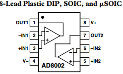
Pinouts

AD8002 pinout

Architecture Insight (CFA vs VFA)

  • Bandwidth is largely independent of gain (unlike voltage feedback amplifiers)
  • Higher slew rate due to current-mode internal nodes
  • Feedback resistor (RF) value is critical for stability and performance
  • Optimized for wideband, high-speed signal paths

Design Notes

  • Carefully select feedback resistor (RF) as per datasheet for stability
  • Use controlled impedance PCB layout for high-frequency signals
  • Minimize parasitic capacitance at input nodes to preserve bandwidth
  • Proper termination (e.g., 50Ω or 75Ω) is required for video applications
  • Decoupling capacitors must be placed close to supply pins
  • Thermal considerations are minimal due to low power but important at high drive currents

Advantages

  • Excellent high-frequency linearity
  • Very fast transient response
  • Capable of driving low impedance loads directly
  • Low power consumption for portable applications
  • Dual amplifier reduces component count

Typical Applications

  • High-speed ADC driver circuits
  • Video line drivers (broadcast and professional video)
  • Differential signal drivers
  • RF front-end buffering
  • Video switchers and multiplexers
  • Imaging systems (cameras, processing units)
  • Special effects and signal processing chains

Alternative / Equivalent Products

  • AD8001 – Single version of high-speed CFA
  • AD812 – High-speed video amplifier
  • LMH6702 – TI ultra-high-speed amplifier
  • THS3202 – TI dual current feedback amplifier
  • OPA695 – Wideband current feedback amplifier

Other data sheets are available within the file:

AD8002AN, AD8002AR, AD8002AR-REEL, AD8002AR-REEL7

AD8002 Datasheet PDF Download


AD8002 pdf