LC7821 Datasheet PDF – Analog Function Switch

Part Number: LC7821

Function: Analog Function Switch

Package: DIP 30 Pin Type

Manufacturer: Sanyo

Images
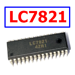
LC7821 datasheet pdf

Description

The LC7821 is a serial data-controlled analog function switch designed for signal routing in amplifiers, receivers, and other analog audio equipment. It contains two groups of eight analog switches, provides a wide signal range supported by ±20V breakdown capability, and includes serial control, device selection, and reset functions for flexible microcomputer-based operation. Typical applications include audio source selection, amplifier signal routing, receiver input switching, and electronically controlled analog signal paths

Features

  • Eight analog switch channels × 2
  • Serial data-controlled analog function selection
  • Designed for use with 5V-operated microcomputers
  • Selector pin allows two ICs of the same type to share a common serial bus
  • Reset input turns OFF all analog switches
  • Wide dynamic range supported by ±20V breakdown voltage
  • Suitable for amplifiers and receivers
  • Multiple internal connection configurations available within the LC7821/LC7822/LC7823 family

Pinout
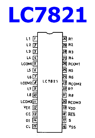
LC7821 pinout

Absolute Maximum Ratings (Tc = 25 °C)

Parameter Symbol Value Unit
Digital input voltage, DI, CL, CE, S, RES VI −0.3 to VDD+0.3 V
Analog terminal voltage, L1 to L8, R1 to R8, LCOM1 to LCOM4, RCOM1 to RCOM4 V VEE−0.3 to VDD+0.3 V
Analog switch ON-state voltage difference ΔVON 0.5 V
Allowable power dissipation Pdmax 100 mW
Operating temperature Topr −30 to +75 °C
Storage temperature Tstg −40 to +125 °C

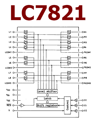
Block Diagram

LC7821 block diagram

Working Principle

  • The LC7821 functions as an electronically controlled analog switch matrix for routing audio or other analog signals between multiple input and common terminals
  • Its two groups of eight switches provide multiple selectable signal paths, making it suitable for stereo source selection in audio equipment
  • Switch states are programmed through serial data rather than individual control lines, substantially reducing the number of microcontroller connections required
  • The DI, CL, and CE control signals provide the serial interface used to transfer and latch switching information into the device
  • The S selector pin allows two devices of the same type to be connected to a common serial bus while providing separate device selection
  • The RES reset input can turn OFF all analog switches, providing a defined disconnected state during startup, shutdown, or fault recovery
  • The analog switch terminals operate between the VEE and VDD supply rails, allowing the signal path to accommodate a comparatively wide analog voltage range
  • The low voltage difference requirement across an ON switch helps maintain the intended analog signal path when the selected channel is active

Applications

  • Audio amplifiers
  • AM/FM receivers
  • Stereo source selectors
  • Audio input routing
  • Electronically controlled analog signal switching
  • Microcomputer-controlled audio equipment
  • Receiver signal-path selection
  • Analog function selection systems

Alternative / Equivalent Products

  • LC7822
  • LC7823

LC7821 Datasheet PDF

LC7821 datasheet

LC7821 pdf

H20R1353 Datasheet PDF – 1350V, 20A, IGBT ( IHW20N135R3 )

Part Number: IHW20N135R3

Function: 1350V, 20A, Reverse conducting IGBT with monolithic body diode

Package: TO247-3 Type

Manufacturer: Infineon ( www.infineon.com )

Images

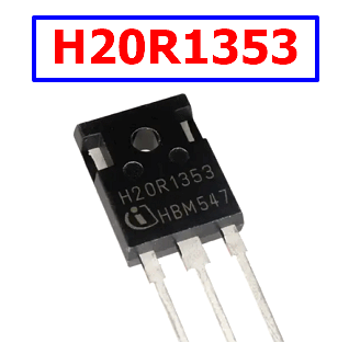
igbt H20R1353 datasheet pdf

Description

H20R1353 is a high-voltage insulated-gate bipolar transistor (IGBT) from the TRENCHSTOP family, designed specifically for resonant and soft-switching power electronics. Its 1350 V collector-emitter rating, high current capability, and integrated monolithic body diode make it particularly suitable for half-bridge and full-bridge power stages where the switching device must tolerate substantial voltage stress while operating with controlled commutation.

From a circuit-design perspective, the IHW20N135R3 combines a high voltage blocking capability with relatively low conduction loss and a diode intended for soft commutation. The positive temperature coefficient of its collector-emitter saturation voltage also makes current sharing between parallel devices more manageable than with devices exhibiting strongly negative thermal behavior.Typical applications include induction cookers, inverterized microwave ovens, resonant power supplies, induction heating equipment, soft-switching DC-DC converters, and other high-frequency power conversion systems.

Features

  • 1350 V collector-emitter rating: The high blocking-voltage capability is one of the main reasons to consider this IGBT in high-voltage resonant converters.
  • 20 A continuous current capability at elevated case temperature
  • 60 A pulsed collector current
  • Integrated body diode: The monolithic diode provides an internal current path during reverse conduction intervals. It is intended for soft commutation, so the circuit should not be designed around unnecessarily aggressive hard reverse-recovery operation.
  • Low VCE(sat): A relatively low saturation voltage helps reduce conduction loss when the IGBT is carrying substantial current. This is particularly useful in resonant converters where the device may conduct high peak currents even though the average power may be lower.
  • Positive temperature coefficient: The positive temperature behavior of VCE(sat) helps distribute current between paralleled IGBTs because a hotter device tends to develop a higher conduction voltage and therefore becomes less attractive for additional current.
  • ±20 V gate-emitter operating range
  • High pulsed current capability
  • Turn-off SOA: The switching stage must remain within the device’s turn-off safe operating area. Voltage, current, temperature, gate resistance, and commutation speed all influence whether the switching event is safe.

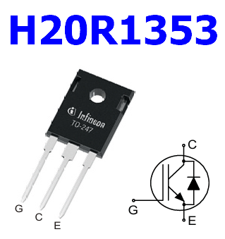
Pinout

igbt H20R1353 pinout

Absolute Maximum Ratings (Tc = 25 °C)

Parameter Symbol Rating Unit
Collector-emitter voltage VCE 1350 V
DC collector current at Tc = 25 °C IC 40.0 A
DC collector current at Tc = 100 °C IC 20.0 A
Pulsed collector current ICpuls 60.0 A
Non-repetitive peak collector current ICSM 200 A
Diode forward current at Tc = 25 °C IF 40.0 A
Diode forward current at Tc = 100 °C IF 20.0 A
Pulsed diode current IFpuls 60.0 A
Gate-emitter voltage VGE ±20 V
Transient gate-emitter voltage, tp ≤ 10 μs, D < 0.010 VGE ±25 V
Power dissipation at Tc = 25 °C Ptot 310.0 W
Power dissipation at Tc = 100 °C Ptot 155.0 W
Operating junction temperature Tvj −40 to +175 °C
Storage temperature Tstg −55 to +175 °C

Typical Circuit Configurations

  • Half-bridge resonant converter: Two IGBTs can form a half-bridge driving an LC resonant network. This arrangement is common in induction heating and other high-frequency power conversion systems.
  • Full-bridge resonant inverter: Four devices can be arranged as a full bridge to apply alternating polarity to a resonant load or transformer primary. The integrated diodes provide current paths during commutation intervals.
  • Series-resonant converter: The IGBT bridge excites a series combination of inductive and capacitive elements. When correctly tuned, the resonant current and voltage waveforms can reduce switching stress.
  • LLC-type resonant stage: An LLC converter can use the IGBT in the primary switching bridge when the operating voltage, switching frequency, and loss profile are compatible with the device.
  • Induction heating inverter: A resonant tank consisting of an induction coil and capacitive network can be driven by a bridge or half-bridge. Soft switching is particularly important because current and voltage can be substantial.

Performance Advantages

  • Large voltage headroom: The 1350 V blocking rating is attractive in systems where DC-link transients make lower-voltage IGBTs uncomfortable from a reliability perspective.
  • Good fit for soft switching: Resonant switching can reduce turn-on and turn-off stress, allowing the device to operate efficiently at frequencies where conventional hard-switched approaches become increasingly lossy.
  • Integrated diode: A monolithic diode eliminates the need for a separately packaged freewheeling diode in many bridge configurations and can simplify the power-stage layout.
  • Low EMI potential: When the switching transition is properly controlled and the commutation is soft, the resulting waveform can reduce the high-frequency energy that commonly creates electromagnetic compatibility problems.

Typical Applications

  • Induction cooktops: Resonant inverter stages require switches capable of handling high voltage and substantial circulating current while maintaining controlled switching losses.
  • Induction heating equipment
  • Inverterized microwave ovens
  • Resonant DC-DC converters
  • Soft-switching power supplies
  • Industrial power electronics

IGBT H20R1353 Datasheet PDF

H20R1353 igbt

H20R1353 pdf