MP3401A Datasheet Pinout – 30V, 3A, P-ch, MOSFET

Part Number: MP3401A

Function: -30V, -3A, P-Channel Enhancement Mode MOSFET

Package: SOT-23 Type

Manufacturer: Major Power TechnologyCo.,Ltd.

Image :

MP3401A datasheet pdf pinout

Features

1. Super High Dense Cell Design

2. Reliable and Rugged

3. Enhance ESD Cell Protection

4. Lead Free and Green Devices Available (RoHS Compliant)

Absolute Maximum Ratings (Ta = 25°C)

1. Drain to source voltage: VDSS = – 30 V

2. Gate to source voltage: VGSS = ± 10 V

3. Drain current: ID = – 3 A

4. Maximum Power Dissipation: Pd = 0.83 W

5. Channel temperature: Tch = 150 °C

6. Storage temperature: Tstg = -55 to +150 °C

Applications

1. Power Management in LCD TV, Monitor, Notebook Computer,

2. Portable Equipment and Battery Powered Systems

or

MP3401 Demo Board Circut

Part Number: MP3401A

Package: SMD 8 pin

Image

MP3401A image

Description

MP3401A is a power bank solution device which is highly integrated with linear charger, LED battery display cell and synchronous boost output. The MP3401A has two operating modes, charge mode and boost mode, to manage the system and battery power based on the state of the input. When input power is present, the MP3401A operates in charge mode. It automatically detects the battery voltage and charges the battery in the three phases: trickle current mode, constant current mode and constant voltage mode. In the absence of input source, MP3401A switches to boost mode automatically when the battery voltage is higher than 3.2V.

Pinout

MP3401A pinout

Features

1. Linear charge, synchronous boost output, built- in power MOS for charge and discharge

2. Charge current:0.7A

3. Maximum boost output current:1A

4. Original temperature technology for boost management

5. C/10 charge terminated and recharge automatically


Other data sheets are available within the file:  MP3401-A


MP3401A Datasheet PDF Download

 pdf

LC7821 Datasheet PDF – Analog Function Switch

Part Number: LC7821

Function: Analog Function Switch

Package: DIP 30 Pin Type

Manufacturer: Sanyo

Images

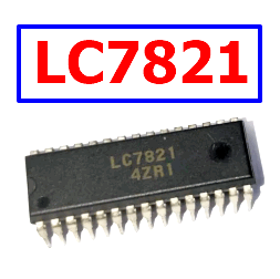
LC7821 datasheet pdf

Description

The LC7821 is a serial data-controlled analog function switch designed for signal routing in amplifiers, receivers, and other analog audio equipment. It contains two groups of eight analog switches, provides a wide signal range supported by ±20V breakdown capability, and includes serial control, device selection, and reset functions for flexible microcomputer-based operation. Typical applications include audio source selection, amplifier signal routing, receiver input switching, and electronically controlled analog signal paths

Features

  • Eight analog switch channels × 2
  • Serial data-controlled analog function selection
  • Designed for use with 5V-operated microcomputers
  • Selector pin allows two ICs of the same type to share a common serial bus
  • Reset input turns OFF all analog switches
  • Wide dynamic range supported by ±20V breakdown voltage
  • Suitable for amplifiers and receivers
  • Multiple internal connection configurations available within the LC7821/LC7822/LC7823 family

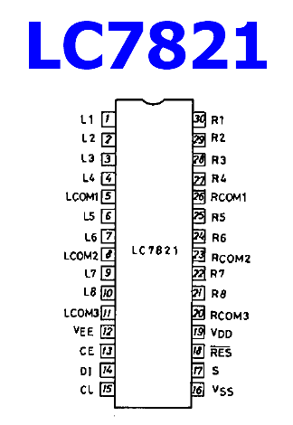
Pinout

LC7821 pinout

Absolute Maximum Ratings (Tc = 25 °C)

Parameter Symbol Value Unit
Digital input voltage, DI, CL, CE, S, RES VI −0.3 to VDD+0.3 V
Analog terminal voltage, L1 to L8, R1 to R8, LCOM1 to LCOM4, RCOM1 to RCOM4 V VEE−0.3 to VDD+0.3 V
Analog switch ON-state voltage difference ΔVON 0.5 V
Allowable power dissipation Pdmax 100 mW
Operating temperature Topr −30 to +75 °C
Storage temperature Tstg −40 to +125 °C

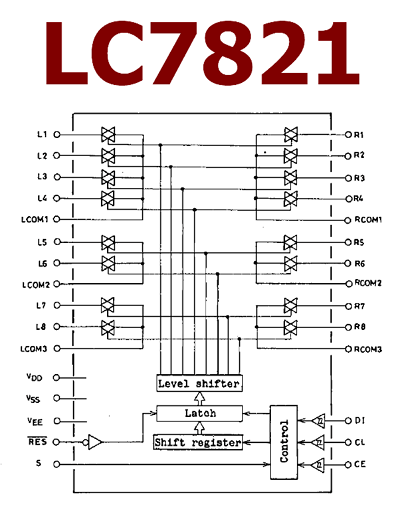
Block Diagram

LC7821 block diagram

Working Principle

  • The LC7821 functions as an electronically controlled analog switch matrix for routing audio or other analog signals between multiple input and common terminals
  • Its two groups of eight switches provide multiple selectable signal paths, making it suitable for stereo source selection in audio equipment
  • Switch states are programmed through serial data rather than individual control lines, substantially reducing the number of microcontroller connections required
  • The DI, CL, and CE control signals provide the serial interface used to transfer and latch switching information into the device
  • The S selector pin allows two devices of the same type to be connected to a common serial bus while providing separate device selection
  • The RES reset input can turn OFF all analog switches, providing a defined disconnected state during startup, shutdown, or fault recovery
  • The analog switch terminals operate between the VEE and VDD supply rails, allowing the signal path to accommodate a comparatively wide analog voltage range
  • The low voltage difference requirement across an ON switch helps maintain the intended analog signal path when the selected channel is active

Applications

  • Audio amplifiers
  • AM/FM receivers
  • Stereo source selectors
  • Audio input routing
  • Electronically controlled analog signal switching
  • Microcomputer-controlled audio equipment
  • Receiver signal-path selection
  • Analog function selection systems

Alternative / Equivalent Products

  • LC7822
  • LC7823

LC7821 Datasheet PDF

LC7821 datasheet

LC7821 pdf