Part Number: HIF3BA-XXX
Function: Ribbon Cable connector Compliant with MIL Standard
Manufacturer: HIROSE ELECTRIC
Image:
Description
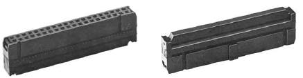
HIF3BA-XXX is a ribbon cable connector series from Hirose, designed in compliance with MIL standards for reliable board-to-cable interconnection. It is intended for use with flat ribbon cables (typically UL2651 AWG#28) and incorporates mechanical polarization features to prevent mis-insertion. The connector is widely used in industrial, instrumentation, and embedded systems requiring robust and repeatable connections.
1. Product Compliant with MIL Standard
HIF3B series has been developed as a product compliant with MIL
standard, and used for wide applications.
2. UL Approval Product
HIF3B series connectors are UL approved.
3. Mechanism to Prevent Mis-insertion
Features
- MIL standard compliant ribbon cable connector
- UL-approved product for safety and reliability
- Supports UL2651 AWG#28 flat ribbon cable
- 2.54 mm pitch (standard IDC spacing)
- Multiple pin counts available (e.g., 6, 10, 14 positions)
- IDC (Insulation Displacement Contact) termination for easy cable assembly
- Reliable mechanical locking and alignment system
Mechanical Characteristics
| Parameter | Description |
| Pitch | 2.54 mm |
| Cable Type | Flat ribbon cable (UL2651, AWG#28) |
| Termination | IDC (Insulation Displacement) |
| Mounting | Cable mount (mates with PCB header) |
Mis-insertion Prevention Mechanism
- Guide-key system aligns connector with mating header
- Polarizing key embedded in socket prevents incorrect orientation
- Mechanical asymmetry ensures correct mating position
Compliance & Certification
- MIL standard compliant design
- UL approved for safety (file varies by model)
Design Notes
- Ensure compatibility with matching Hirose HIF3B series pin headers
- Use proper IDC crimping tool to ensure reliable termination
- Maintain correct cable orientation to match polarization key
- Verify pin count and pitch for system compatibility
- Consider strain relief for high-vibration environments
How to Choose This Part
- Select based on required number of positions (e.g., 6, 10, 14 pins)
- Ensure compatibility with AWG#28 ribbon cable
- Verify mating connector (header) type and pitch
- Choose variants with locking features if vibration resistance is required
Typical Applications
- Board-to-cable interconnections
- Industrial control systems
- Instrumentation and measurement equipment
- Embedded systems and computing interfaces
Alternative / Equivalent Products
- Hirose HIF3B header series
- TE Connectivity IDC ribbon connectors
- Amphenol FCI ribbon cable connectors
- 3M IDC socket connectors
Other data sheets are available within the file:
HIF3BA- 6D-2.54R , HIF3BA-10D-2.54R , HIF3BA-14D-2.54R
HIF3BA-16D-2.54R , HIF3BA-20D-2.54R , HIF3BA-26D-2.54R
HIF3BA-30D-2.54R , HIF3BA-34D-2.54R , HIF3BA-40D-2.54R
HIF3BA-50D-2.54R , HIF3BB-50D-2.54R , HIF3BA-60D-2.54R
HIF3BB-60D-2.54R , HIF3BA-64D-2.54R , HIF3BB-64D-2.54R
HIF3BA-XXX Datasheet PDF Download