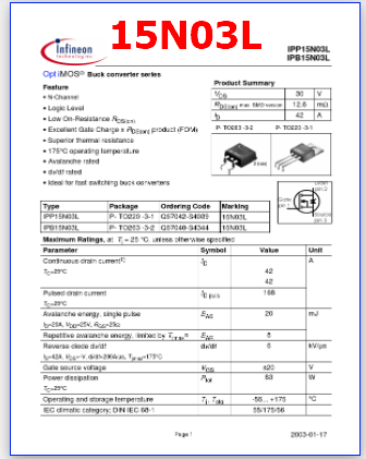
Part Number: 15N03L, IPP15N03L
Function: 30V, 42A, Buck converter
Package: TO-220, TO-263 Type
Manufacturer: Infineon Technologies AG
Images:
Description
15N03L is OptiMOS Buck converter.
1. Texas Instruments TPS56xx Series: This series of buck converters from Texas Instruments offers a wide range of options, including adjustable and fixed output voltage versions. They are known for their high efficiency, wide input voltage range, and advanced features such as voltage tracking and sequencing.
2. Analog Devices LT8614/LT8615: The LT8614 and LT8615 from Analog Devices are highly efficient synchronous buck converters designed for high-current applications. They offer excellent load and line regulation, low dropout voltage, and a wide input voltage range.
3. Maxim Integrated MAXM175xx Series: Maxim Integrated’s MAXM175xx series provides highly integrated buck converters with high efficiency, low quiescent current, and compact form factors. They are suitable for space-constrained applications and offer features such as programmable soft-start and integrated power switches.
4. STMicroelectronics L798x Series: The L798x series from STMicroelectronics offers a range of buck converters with high efficiency, wide input voltage range, and adjustable output voltage options. They are known for their robust performance and thermal management features.
5. ON Semiconductor NCP156x Series: ON Semiconductor’s NCP156x series of buck converters are designed for high-performance applications. They provide high efficiency, fast transient response, and a wide input voltage range. They also offer protection features such as overcurrent protection and thermal shutdown.
Feature:
• N-Channel Product Summary VDS RDS(on) max. SMD version ID P- TO263 -3-2 30 12.6 42 P- TO220 -3-1 V mΩ A • Logic Level • Low On-Resistance RDS(on) • Excellent Gate Charge x RDS(on) product (FOM) • Superior thermal resistance • 175°C operating temperature • Avalanche rated • dv/dt rated • Ideal for fast switching buck converters
Package Ordering Code Marking 15N03L 15N03L P- TO220 -3-1 Q67042-S4039 P- TO263 -3-2 Q67040-S4344 Maximum Ratings, at Tj = 25 °C, unless otherwise specified Parameter Symbol Continuous drain current1) TC=25°C Value 42 42 Unit A ID Pulsed drain current TC=25°C I D puls EAS EAR dv/dt VGS Ptot T j , Tstg 168 20 8 6 ±20 83 -55… +175 55/175/56 kV/µs V W °C mJ Avalanche energy, single pulse ID=20A, VDD=25V, RGS=25Ω Repetitive avalanche energy, limited by Tjmax2) Reverse diode dv/dt IS=42A, VDS=-V, di/dt=200A/µs, Tjmax=175°C Gate source voltage Power dissipation TC=25°C Operating and storage temperature IEC climatic category; DIN IEC 68-1 Page 1 2003-01-17 IPP15N03L IPB15N03L Thermal Characteristics Parameter Characteristics Thermal resistance, junction – case SMD version, device on PCB: @ min. footprint @ 6 cm2 cooling area 3) Symbol min. RthJC RthJA – Values typ. 1.2 max. 1.8 62 40 Unit K/W Electrical Characteristics, at Tj = 25 °C, unless otherwise specified Parameter Static Characteristics Drain-source breakdown voltage V GS=0V, I D=1mA Symbol min. V(BR)DSS VGS(th) I DSS I GSS RDS(on) RDS(on) 30 1.2 Values typ. 1.6 max. 2 Unit V Gate threshold voltage, VGS = VDS ID=40µA Zero gate voltage drain current V DS=30V, V GS=0V, Tj=25°C V DS=30V, V GS=0V, Tj=125°C µA 0.01 10 1 1 100 100 nA mΩ 14.9 14.5 10.3 9.9 19.9 19.6 12.9 12.6 Gate-source leakage current V GS=20V, VDS=0V Drain-source on-state resistance V GS=4.5V, ID=21A V GS=4.5V, ID=21A, SMD version Drain-source on-state resistance V GS=10V, ID=21A V GS=10V, ID=21A, SMD version 1Current limited by bondwire ; with an R thJC = 1.8K/W the chip is able to carry I D= 64A at 25°C, for detailed information see app.-note ANPS071E available at www.infineon.com/optimos 2Defined by design. Not subject to production test. 3Device on 40mm*40mm*1.5mm epoxy PCB FR4 with 6cm² (one layer, 70 µm thick) copper area for drain connection. PCB is vertical without blown air. Page 2 2003-01-17 IPP15N03L IPB15N03L Electrical Characteristics Parameter Dynamic Characteristics Transconductance Input capacitance Output capacitance Reverse transfer capacitance Gate resistance Turn-on delay time Rise time Turn-off delay time Fall time Gate Charge Characteristics Gate to source charge Gate to drain charge Gate charge total Output charge Gate plateau voltage Reverse Diode Inverse diode continuous forward current Inv. diode direct current, pulsed Inverse diode forward voltage Reverse recovery time Reverse recovery charge ISM VSD trr Qrr VGS =0 […]

15N03L PDF Datasheet