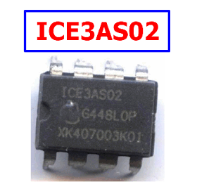
Part Number: ICE3AS02
Function: Off-Line SMPS Current Mode Controller with integrated 500V Startup Cell
Package: DIP 8 Pin type
Manufacturer: Infineon Technologies
Images :
Description
ICE3AS02 is an off-line SMPS current-mode controller with an integrated 500V startup cell, designed for compact flyback power supplies and available in an 8-pin package.
The F3 Controller provides Active Burst Mode to reach the lowest Standby Power Requirements <100mW at no load. As the controller is always active during Active Burst Mode, there is an immediate response on load jumps without any black out in the SMPS. In Active Burst Mode the ripple of the output voltage can be reduced <1%.
Features
1. Active Burst Mode for lowest Standby Power @ light load controlled by Feedback Signal
2. Fast load jump response in Active Burst Mode
3. 500V Startup Cell switched off after Start Up
4. 100/67kHz internally fixed switching frequency
5. Auto Restart Mode for Overtemperature Detection
6. Blanking Window for short duration high current
7. User defined Soft Start
8. Minimum of external components required
ICE3AS02 Pinouts

Pin Functionality
SoftS (Soft Start & Auto Restart Control)
The SoftS pin combines the functions of Soft Start during Start Up and error detection for Auto Restart Mode. These functions are implemented and can be adjusted by means of an external capacitor at SoftS to ground. This capacitor also provides an adjustable blanking window for high load jumps,
before the IC enters into Auto Restart Mode.
FB (Feedback)
The information about the regulation is provided by the FB Pin to the internal Protection Unit and to the internal PWM Comparator to control the duty cycle. The FB-Signal controls in case of light load the Active Burst Mode of the controller.
CS (Current Sense)
The Current Sense pin senses the voltage developed on the series resistor inserted in the source of the external PowerMOS. If CS reaches the internal threshold of the Current Limit Comparator, the Driver output is immediately switched off. Furthermore the current information is provided for the PWM-Comparator to realize the Current Mode.
Gate
The Gate pin is the output of the internal driver stage connected to the Gate of an external PowerMOS.
HV (High Voltage)
The HV pin is connected to the rectified DC input voltage. It is the input for the integrated 500V Startup Cell.
VCC (Power supply)
The VCC pin is the positive supply of the IC. The operating
range is between 8.5V and 21V.
GND (Ground)
The GND pin is the ground of the controller.
Product Highlights
• Active Burst Mode to reach the lowest Standby Power Requirements < 100mW
• Protection features (Auto Restart Mode) to increase robustness and safety of the system
• Adjustable Blanking Window for high load jumps to increase system reliability
• PB-free Plating and RoHS compilant
Applications
- Off-line flyback power supplies
- AC-DC adapters
- Low-power isolated SMPS
- Standby power supplies
- Auxiliary power supplies
- Consumer electronic power supplies
- Compact embedded power converters
- Low-standby-power switching power supplies
Other data sheets are available within the file: ICE3BS02, ICE3AS02G, ICE3BS02G, Q67040-S4637-A101
ICE3AS02 Datasheet PDF Download