Part Number: TDA8961
Function: ATSC Digital Terrestrial TV Demodulator / Decoder
Package: QFP 80 Type
Manufacturer: Philips Electronics ( https://www.nxp.com/ )
Pinouts:
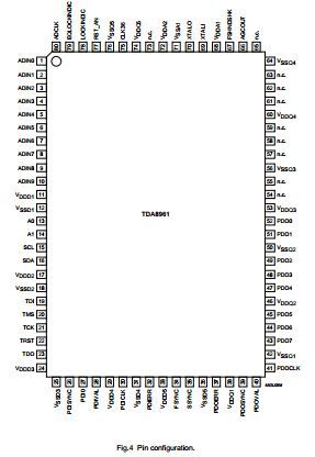
Description
The TDA8961 is an Advanced Television Systems Committee (ATSC)-compliant demodulator and FEC decoder for reception of 8-VSB modulated signals for terrestrial and cable applications:
1. Terrestrial: reception of 8-VSB modulated signals via standard 6 MHz VHF/UHF terrestrial TV channels (TV channels 2 to 69 in the United States).
2. Cable: reception of 8-VSB modulated signals via standard 6 MHz VHF/UHF cable TV channels.
General features :
• One-chip ATSC-compliant demodulator and concatenated trellis (Viterbi)/Reed Solomon decoder with de-interleaver and de-randomizer
• 0.35µm process
• 3.3 V device
• QFP80 package
• Boundary Scan Test (BST)
• 12 MHz external clock
• 36 MHz output for external D/A converter
• Parallel or serial MPEG-2 transport stream output.
8-Vestigial Side Band (VSB) demodulator :
• Accepts 10-bit IF data sampled at 36 MHz
• 6 MHz wide IF signal, centered at 4 MHz
• On-chip digital circuitry for tuner AGC
• Square-root raised-cosine filter with 11.5% roll-off factor
• Fully internal carrier recovery loop
• No need for external voltage controlled crystal oscillator due to internal sample rate converter
• Fully internal symbol timing recovery with programmable loop filters
• Technology to handle dynamic multipath conditions.
TDA8961 Datasheet PDF Download


Other data sheets are available within the file: 8961, TDA-8961


