Part Number: LCM1602C
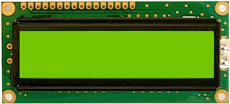
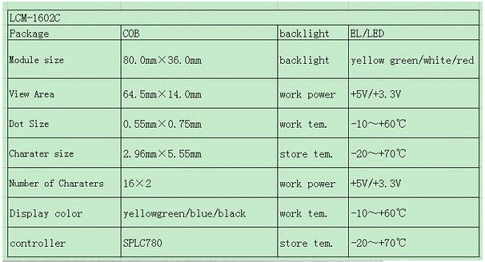
Function: LCD display, 1602 5V Yellow-Green/Blue
Package: Module Type
Imags :
Description
This is 16 char x 2 line, LCD Display.
Features
- Pin 1 is connected directly to ground.
- Pin 2 is connected directly to +5V. (NOTE: This, in turn, comes directly from the +5V output of the Arduino Uno.)
- Pin 3 is connected to the middle pin of the 10k potentiometer, and is used to adjust the contrast of the LCD.
- Pin 4 (RS or “register select”) is connected to pin 12 on the Arduino Uno.
- Pin 5 (RW or “read/write”) is connected directly to ground. By doing this, we’re saying that we’re only going to write to the LCD, not read anything from it. Which is fine. We just want to put text onto the LCD, not read anything from it anyway.
- Pin 6 (EN or “enable”) is connected to pin 11 on the Arduino Uno.
- Pins 7 – 10: Not connected.
- Pin 11 on the LCD is connected to pin 5 on the Arduino Uno.
- Pin 12 on the LCD is connected to pin 4 on the Arduino Uno.
- Pin 13 on the LCD is connected to pin 3 on the Arduino Uno.
- Pin 14 on the LCD is connected to pin 2 on the Arduino Uno.
- Pin 15 is connected to one end of a 1k resistor, and the other end of the resistor is connected to 5V.
- Pin 16 is connected directly to ground.
Reference Site:
1. http://www.ntscope.com/LCD1602C.html
2. Cómo controlar una pantalla LCD con Arduino (comohacer.eu)
3. Understanding the LCM1602C LCD Display
4. https://www.adafruit.com/datasheets/TC1602A-01T.pdf
LCM1602C Datasheet PDF Download


