AD8128 Datasheet PDF – CAT-5 Receiver

Part Number: AD8128

Function: CAT-5 Receiver with Adjustable Line Equalization

Package: Small 8-lead 3 mm × 3 mm LFCSP Type

Manufacturer: Analog Devices

Pinouts:

AD8128 datasheet


Description

The AD8128 is a high speed, differential receiver/equalizer that compensates for the transmission losses of unshielded twisted pair (UTP) CAT-5 cables. Various frequency dependent gain stages are summed together to best approximate the inverse frequency response of CAT-5/CAT-5e cable.

An equalized bandwidth of 120 MHz can be achieved for 100 meters of cable. The AD8128 can be used as a standalone receiver/equalizer or in conjunction with the AD8143, triple differential receiver, to provide a complete low cost solution for receiving RGB over UTP cable in such applications as KVM. The AD8128 has three control pins for optimal CAT-5/CAT-5e compensation. The equalized cable length is directly proportional to the voltage applied to the VPEAK pin, which controls the amount of high frequency peaking. VGAINadjusts the broadband gain from 0 dB to 3 dB, compensating for the resistive cable loss. VOFFSETallows the output to be shifted by ±2.5 V, adding flexibility for dc-coupled systems.

Features

– Tuned to compensate for Category-5 (CAT-5) cable losses
– Up to 100 meters @ 120 MHz
– 2 voltage-controlled frequency response adjustment pins
– High frequency peaking adjustment
– Broadband gain adjustment
– 2700 V/μs slew rate
– Low output noise
– 1.5 mV rms integrated noise (1 GHz) @ 100 meters
– equalized bandwidth
– DC output offset adjust
– Low offset voltage error: 7 mV typ
– Equalized pass-band ripple ±1 dB to 70 MHz
– Input: differential or single ended
– Supply current: 24 mA on ±5 V
– Small 8-lead 3 mm × 3 mm LFCSP

Applications

– Keyboard-video-mouse (KVM)
– RGB video over unshielded twisted pair (UTP) cable receivers
– Professional video projection and distribution
– Security video

Other data sheets are available within the file:

AD8128ACPZ-R2, AD8128ACPZ-R7, AD8128ACPZ-RL

AD8128 Datasheet PDF Download


AD8128 pdf

MAX232CPE Datasheet – RS-232 Drivers / Receivers – Maxim

This IC is dual driver/receiver.

Part Number: MAX232CPE

Function: +5V-Powered, Multichannel RS-232 Drivers/Receiver

Package: 16 Pin DIP Type

Manufacturer: Maxim Integrated

Image

max232cpe-rs-232-driver-receiver-maxim


Description

The MAX220 Thru MAX249 family of line drivers/receivers is intended for all EIA/TIA-232E and V.28/V.24 communications interfaces, particularly applications where ±12V is not available.

These parts are especially useful in battery-powered systems, since their low-power shutdown mode reduces power dissipation to less than 5µW. The MAX225, MAX233, MAX235, and MAX245/MAX246/MAX247 use no external components and are recommended for applications where printed circuit board space is critical.

The MAX220-MAX249 are offered in 26 different packages with temperatures from 0 to +70°C up to -55°C to +125°C. See ordering information table at the end of the data sheet for all package and temperature options.
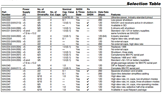
max232 Datasheet Selection Table

Applications/Uses

1. Battery-Powered RS-232 Systems
2. Interface Translation
3. Low-Power Modems
4. Multidrop RS-232 Networks
6. Portable Computing

MAX232CPE Drivers

The typical driver output voltage swing is ±8V when loaded with a nominal 5kΩRS-232 receiver and VCC= +5V. Output swing is guaranteed to meet the EIA/TIA-232E and V.28 specification, which calls for ±5V minimum driver output levels under worst-case conditions. These include a minimum 3kΩload, VCC= +4.5V, and maximum operating temperature. Unloaded driver output voltage ranges from (V+ -1.3V) to (V- +0.5V).


Pinout

max232cpe-datasheet-pinout


MAX232CPE Receivers

EIA/TIA-232E and V.28 specifications define a voltage level greater than 3V as a logic 0, so all receivers invert. Input thresholds are set at 0.8V and 2.4V, so receivers respond to TTL level inputs as well as EIA/TIA-232E and V.28 levels. The receiver inputs withstand an input overvoltage up to ±25V and provide input terminating resistors with nominal 5kΩ values. The receivers implement Type 1 interpretation of the fault conditions of V.28 and EIA/TIA-232E.

Reference Site: [ Wikipedia MAX232 Info ]

MAX232CPE Datasheet PDF

MAX232 pdf


Other data sheets are available within the file: MAX220 Thru MAX249, MAX222C-D, MAX223C-D

Related articles across the web