Part Number: LM5001-Q1
Function: 3.1-75V Wide Vin, 1A Current Mode Non-Synchronous Switch Mode Regulator
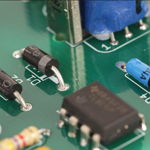
Package: SOIC 8 Pin Type
Manufacturer: Texas Instruments
Pinouts:

Description
The LM5001-Q1 high-voltage switch-mode regulator features all of the functions necessary to implement efficient high-voltage Boost, Flyback, SEPIC and Forward converters, using few external components.
This easy-to-use regulator integrates a 75-V N Channel MOSFET with a 1-A peak current limit. Current mode control provides inherently simple loop compensation and line-voltage feed-forward for superior rejection of input transients. The switching frequency is set with a single resistor and is programmable up to 1.5 MHz. The oscillator can also be synchronized to an external clock. Additional protection features include: current limit, thermal shutdown, undervoltage lockout and remote shutdown capability.
High-Voltage VCC Regulator
The LM5001 VCC Low Drop Out (LDO) regulator allows the LM5001 to operate at the lowest possible input voltage. The VCC pin voltage is very nearly equal to the input voltage from 2.8 V up to approximately 6.9 V. As the input voltage continues to increase, the VCC pin voltage is regulated at the 6.9 V set-point. The total input operating range of the VCC LDO regulator is 3.1 V to 75 V.
The output of the VCC regulator is current limited to 20 mA. During power up, the VCC regulator supplies current into the required decoupling capacitor (0.47 µF or greater ceramic capacitor) at the VCC pin. When the voltage at the VCC pin exceeds the VCC UVLO threshold of 2.8 V and the EN pin is greater than 1.26 V the PWM controller is enabled and switching begins. The controller remains enabled until VCC falls below 2.7 V or the EN pin falls below 1.16 V.
Features
1. Integrated 75-V N-Channel MOSFET
2. Ultra-Wide Input Voltage Range from 3.1 V to 75 V
3. Integrated High Voltage Bias Regulator
4. Adjustable Output Voltage
5. 1.5% Output Voltage Accuracy
6. Current Mode Control with Selectable Compensation
Official Site : https://www.ti.com/product/lm5001-q1
LM5001-Q1 Datasheet


Other data sheets are available within the file: LM5001, LM5001Q1