The TL431 is designed to provide a stable voltage reference with adjustable output voltage by changing the resistor values connected to its reference and cathode terminals. The device can operate in a wide range of input voltage and is commonly used to regulate voltage in power supplies, battery chargers, and other electronic circuits.
Part Number: TL431
Function: Programmable Shunt Regulator
Package: TO 92, DIP 8, SOP 8 Pin
Manufacturer: Fairchild Semiconductor
Image
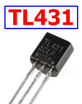
What is TL431?
The TL431, TL431A are three-terminal adjustable regulator series with a guaranteed thermal stability over applicable temperature ranges. The output voltage may be set to any value between VREF(approximately 2.5 volts) and 36 volts with two external resistors These devices have a typical dynamic output impedance of 0.2Ω. Active output circuitry provides a very sharp turn-on characteristic, making these devices excel lent replacement for zener diodes in many applications.
TL431 Advantages Vs Disadvantages
Advantages:
1. Provides stable and accurate voltage reference and regulation
2. Can be adjusted to various output voltages
3. Can operate in a wide range of input voltages
4. Easy to use and widely available
5. Low cost compared to other precision voltage regulators
Disadvantages:
1.. Requires external resistors to set the output voltage, which can add complexity to the circuit
2. Output voltage can drift with temperature and aging
3. Limited current handling capability compared to other voltage regulators
4. May require additional circuitry for some applications, such as current limiting or voltage clampin
Pinout:
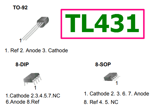
Features
1. Programmable Output Voltage to 36 Volts
2. Low Dynamic Output Impedance 0.2ΩTypical
3. Sink Current Capability of 1.0 to 100mA
4. Equivalent Full-Range Temperature Coefficient of 50ppm/°C Typical
5. Temperature Compensated For Operation Over Full Rated Operating Temperature Range
6. Low Output Noise Voltage
7. Fast Turn-on Response
Block Diagram
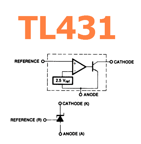
Reference Site: https://www.onsemi.com/PowerSolutions/product.do?id=TL431
FAQs
1. How do I adjust the output voltage of this IC?
The output voltage of TL431 can be adjusted by connecting a resistor between the reference and cathode terminals. The value of the resistor determines the output voltage, according to the formula Vout = Vref x (1 + R2/R1), where Vref is the reference voltage (usually 2.5V), R1 is the resistor connected to the reference terminal, and R2 is the resistor connected to the cathode terminal.
2. Can TL431 be used as a voltage detector?
Yes, This IC can be used as a voltage detector by connecting a voltage divider between the input voltage and reference terminal. When the input voltage exceeds the reference voltage, the TL431 turns on and conducts current, indicating that the input voltage has reached a certain threshold. This application is commonly used for overvoltage protection and battery voltage monitoring.
TL431 Datasheet PDF Download

Other data sheets are available within the file: TL431A, TL431ACD, TL431ACLP, TL431CD