LA78141 Datasheet PDF – Vertical Deflection Output IC – Sanyo

This is a vertical deflection output IC.

Part Number: LA78141, LA78141-E

Function: Vertical Output, Vertical Drive, Pump-up

Package: TO-220-7H Plastic Type

Manufacturer: Sanyo Semiconductor

See the preview image and the PDF file for more information.

Image
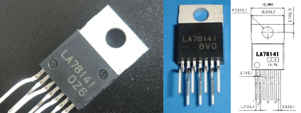
LA78141 image

Description

The Sanyo LA78141 is an integrated circuit (IC) designed for use in television sets and other video applications. It is a vertical deflection output IC that controls the vertical scanning of the display screen. The device can drive a large deflection coil with a high output current, making it ideal for use in larger displays. Additionally, it has built-in thermal protection and over-current protection, ensuring safe and reliable operation.

The LA78141 is a vertical deflection output IC for high image quality TV and CRT displays that supports the use of a bus control system signal-processing IC.

The sawtooth waveform from the bus control system signal-processing IC can directly drive the deflection yoke (including the DC component). Color TV vertical deflection system adjustment functions can be controlled over a bus system by connecting the LA78141N to a Sanyo LA768X series or LA769XX series bus control system signal-processing IC.

Key Features

  • High output current capability → suitable for large CRT displays
  • Built-in thermal protection circuit
  • Integrated over-current protection
  • Supports direct sawtooth waveform input
  • Compatible with Sanyo LA768x / LA769xx series system ICs
  • High linearity for improved vertical geometry

Specifications
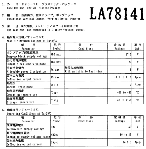
LA78141 datasheet pdf

Core Function

  • Vertical deflection output amplifier
  • Direct drive of vertical deflection yoke (including DC component)
  • Interface with bus-controlled video processor ICs

LA78141 Pinout

LA78141 Circuit

  1. Invertin Input
  2. VCC
  3. Pump Up Out
  4. Gnd
  5. Ver.Out
  6. Output  Stage VCC
  7. Non Inv.Input Multimedia Misc – Vertical Output IC

Block Diagram
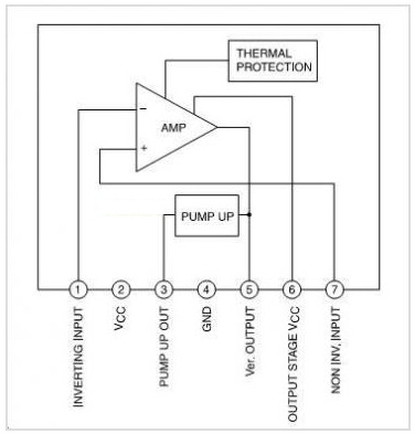
LA78141 pinout

Absolute maximum ratings ( Ta=25°C )

1. Pump-up block supply voltage : +B2 max = 37.5 V

2. Ouput block supply voltage : +B6 max = 77 V

3. Allowalbe power dissipation : pd max = 9 W

LA78141 Application circuits

LA78141-E Application Circuit Example


Advantages

  • High current drive capability
  • Integrated protection → improved reliability
  • Reduced external component count
  • Compatible with bus-controlled TV systems

Multimedia Misc – Vertical Output IC

LA78141-E image

Typical Applications

  • CRT televisions (14″ ~ 29″ and above)
  • CRT monitors
  • Video display systems using analog deflection
  • Bus Supported TV Display Vertical Output

Related ICs

  • LA78040 (lower power variant)
  • LA78145 / LA78141N (package or performance variants)
  • TDA8172 / TDA3653 (alternative vertical output ICs)

Related Posts

 LA78141 Datasheet PDF

LA78141 pdf

Posted in Uncategorized Tagged

NEMA23 Datasheet – 2-phase Hybrid Stepper Motor

The NEMA23 is a 2-phase hybrid stepper motor designed for precision motion control, featuring a 1.8° step angle and a robust mechanical structure in a 3.1-inch motor body.

Pacakge: 2.3 x 2.3 inch (58.4 x 58.5 mm)

Manufacturer: Schneider Electric

This post explains for the Stepper Motor NEMA 23.

Image

NEMA 23 datasheet

Description

Nema 23 is a stepper motor with a 2.3 x 2.3 inch faceplate. It is suitable for 3d printer, robot arm, cnc machine,etc. In low-speed applications, the stepper motor can be driven at the desired speed without missing a single step. It delivers high holding torque with stable current characteristics, making it well-suited for applications requiring accurate positioning and repeatability. This motor is commonly deployed in CNC systems, additive manufacturing equipment, and automated industrial machinery.

This stepper motor has different torque, the max torque is 3 Nm. We provide nema 23 stepper motor datasheet and torque curve. The torque is different for each operating speed, but decreases as the stepping speed increases. The reason is the operating principle of the stepper motor. The drive signal of the stepper motor generates a magnetic field in the coil of the motor to generate a step force. The time it takes for the magnetic field to reach its maximum intensity depends on the inductance of the coil, the drive voltage and current limit. As the drive speed increases, the coil maintains its full strength for a shorter period of time and the torque that the motor can produce decreases.

NEMA23 Pinout

NEMA 23 pinout

Features

  • NEMA23 standard frame size for wide mechanical compatibility
  • 2-phase hybrid stepper motor with 1.8° step angle
  • High holding torque of 270 oz·in for reliable load handling
  • Rated current of 2.8A per phase
  • Low phase inductance for improved dynamic response
  • Four-lead configuration optimized for bipolar drive
  • Suitable for microstepping control systems

Wiring and Connections

Signals and wire colors   2.4 Amp motors   3.0 Amp motors    6.0 Amp motors
Phase A                        Red                      Red                  Black
Phase /A                  White / red           White / red             Orange
Phase B                     Green                    Green                   Red
Phase /B                  White / green        White / green           Yellow


Specifications

1. Voltage Rating : 3.2V
2. Current Rating : 2.8A
3. Holding Torque : 270 oz. in
4. Step Angle : 1.8 deg.
5. Steps Per Revolution : 200
6. No. of Phases : 4
7. Motor Length : 3.1 inches
8. No. of Leads : 4
9 Inductance Per Phase : 3.6mH

Design Notes

  • Use a constant-current chopper driver to achieve optimal torque performance
  • Higher supply voltages improve high-speed performance when current is properly limited
  • Ensure adequate motor cooling during continuous high-torque operation
  • Rigid mechanical mounting helps maintain positioning accuracy

Typical Circuit Usage

  • Bipolar stepper driver controlling two motor phases
  • Microstepping controller for smooth motion and reduced vibration
  • Current sense resistors for precise phase current regulation
  • Controller interface via STEP/DIR or motion control signals

Applications

  • CNC machines and milling systems
  • 3D printers and prototyping platforms
  • Laser cutters and engraving machines
  • Pick-and-place automation equipment
  • Precision motion control systems

Reference Sites

1. NEMA 23 Stepper Motor  with Arduino (microcontrollerslab.com)
2. https://howtomechatronics.com/tutorials/arduino
3. NEMA17 Datasheet – Stepper Motor (datasheetcafe.com)


NEMA23 Datasheet PDF Download

NEMA23 pdf


nema 23 vs nema 17

Similar features and reference parts ( NEMA17 )