JQC-3F Datasheet PDF – PCB Relay ( 10A, 3V to 24V DC )

Part Number: JQC-3F

Function: PCB Relay ( High-Power Electromagnetic Relay )

Package: 5 Pin DIP Type

Manufacturer: Tongling, HWE ( Yueqing Hengwei Electronics )

Image:

Relay JQC-3F Datasheet

Description

The JQC-3F is a general-purpose electromagnetic PCB relay (single pole changeover / SPDT) commonly offered in coil voltages from 3V to 24V DC. It supports load switching up to around 10A at 250VAC or 30VDC with silver alloy contacts in a compact footprint. This relay is used wherever isolation between control logic and power circuits is needed and space is limited.

Features

1. Contact Form 1A, 1C

2. Contact material : AgCdO

3. Contact Resistance : < 100 Mohm ( 1A 6VDC )

4. Switching Current : 10 A

5. Rated Load : 10A 250VAC/30VDC

Pinouts

JQC-3F pinout

Absolute Maximum Ratings (Ta = 25 °C)

Parameter Symbol Value Unit
Maximum switching voltage VSW 250 VAC / 30 VDC
Maximum switching current ISW 10 A
Coil power Pcoil 0.36 / 0.45 W
Insulation resistance (min) Rins 100 MΩ
Dielectric (coil ↔ contacts) Vdiel1 1500 VAC
Dielectric (open contacts) Vdiel2 750 VAC
Operate time max top 10 ms
Release time max trel 5 ms
Ambient temperature range Tamb –40 to +85 °C

Applications

  • Switching loads in home appliances (e.g. motors, lighting)
  • Control and automation systems requiring isolation
  • Power supply soft start or bypass switching
  • Audio and instrument switching
  • General purpose relay use in industrial electronics

Alternative / Equivalent Products

  • HF3FF (Hongfa) series 10A SPDT relay :contentReference[oaicite:8]{index=8}
  • Songle SRD-05VDC-CL 10A relay (common miniature relay)
  • Panasonic TQ2SA series miniature general purpose relay
  • Omron G5LE series 10A general purpose relay
  • TE / Potter & Brumfield PB series 10A signal relays

Other data sheets are available within the file:

JQC-3F1ADC12V, JQC-3F1ADC24V, JQC-3F1CDC12V, JQC-3F1CDC24V

JQC-3F Datasheet PDF Download


JQC-3F pdf

STR-W6753 Datasheet PDF – Switching Regulator – Allegro

Part Number: STR-W6753, STRW6753, STRW-6753

Function: Quasi-Resonant Switching Regulator

Package: TO-220-7 Pin Type

Manufacturer: Allegro MicroSystems

Images:

STR-W6753 image

Description

The STR-W6753 is a quasi-resonant regulator specifically designed to satisfy the requirements for increased integration and reliability in switch-mode power supplies. It incorporates a primary control and drive circuit with an avalanche-rated power MOSFET. The regulator exhibits only low-level high-frequency EMI noise because of soft switching of the MOSFET close to ground (bottom point). A bottom-skip function minimizes an increase of operational frequency during light loads to improve system efficiency over the entire load range.

Key Architecture

  • Integrated PWM controller + 650V avalanche-rated MOSFET
  • Quasi-resonant (QR) switching for low switching loss
  • Valley switching (turn-on near VDS minimum)
  • Primary-side control (no optocoupler required in some designs)
  • Burst mode operation for light-load efficiency

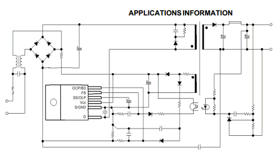
Application circuts

STR-W6753 Datasheet

Features

1. Rugged 650 V Avalanche-Rated MOSFET Simplified Surge Absorption No VDSS Derating Required

2. 1.7 Ω Maximum rDS(on)

3. Two Operational Modes by Automatic Switching :
(1) Quasi-Resonant Mode for Normal Operation
(2) Burst Mode for Standby Operation or Light Loads

4. Automatic or Manually Triggered Burst Standby Input Power <0.1 W at No Load

5. Low Operating Current (6 mA typ)


Absolute maximum ratings

1. Control Supply Voltage : VCC = 35 V

2. Drain-Source Voltage : VDSS = 650 V

3. Drain Switching Current : ID = 11.2 A

4. Peak Drain Switching Current : IDM = 11.2 A

5. Single-Pulse Avalanche Energy : EAS = 145 mJ

6. Package Power Dissipation : PD = 0.8 W


Typical Circuit Usage

  • AC-DC flyback converter (85~265VAC input)
  • CRT / LCD TV power supply
  • Set-top box SMPS
  • Adapters and chargers (low to mid power)
  • Auxiliary standby power supplies

Design Notes (Critical Points)

  • Transformer design is key (QR operation depends on resonance timing)
  • Snubber network still required, but can be simplified
  • Ensure proper VCC startup resistor and auxiliary winding design
  • Thermal design must consider internal MOSFET dissipation
  • Layout: minimize loop area of primary switching path

Advantages vs Conventional PWM Flyback

  • Lower switching loss (valley switching)
  • Lower EMI (soft switching)
  • Higher efficiency at light load (burst mode)
  • Reduced external components

Applications

  • TV SMPS (very common in CRT/LCD designs)
  • Consumer electronics power supplies
  • Industrial auxiliary power
  • Low standby power designs (Energy Star compliant)

Alternative / Equivalent Products

  • STR-W6754 / STR-W6756 (higher power variants)
  • NCP1207 (ON Semiconductor)
  • ICE2QR series (Infineon)
  • TNY277 (Power Integrations – lower power range)

Other data sheets are available within the file: STRW6753

STR-W6753 Datasheet PDF Download


STR-W6753 pdf