BQ29412 Datasheet PDF – Overvoltage Protection IC

Part Number: BQ29412

Function: VOLTAGE PROTECTION FOR 2-, 3-, OR 4-CELL Li-Ion BATTERIES

Package: TSSOP, SM8 Type

Manufacturer: Texas Instruments

Pinouts:

BQ29412 datasheet


Description

BQ29412 is a secondary overvoltage protection IC designed for 2- to 4-cell lithium-ion battery packs, featuring a fixed 4.45V high-accuracy detection threshold in a compact package. It integrates precise voltage monitoring, programmable delay timing, and strong ripple rejection to ensure stable operation even under pulse charging conditions. This device is commonly used in battery protection circuits for portable electronics and energy storage systems.

Features

  • Fixed high-accuracy overvoltage protection threshold (4.45V per cell)
  • Supports 2-, 3-, and 4-cell lithium-ion battery packs
  • Programmable delay time for overvoltage detection
  • High power supply ripple rejection capability
  • Stable operation during pulse charging conditions
  • Low current consumption for battery-powered systems

• Fixed High Accuracy Overvoltage Protection Threshold
– bq29410 = 4.35 V
– bq29411 = 4.40 V
– bq29412 = 4.45 V
– bq29413 = 4.50 V
– bq29414 = 4.55 V
– bq29415 = 4.60 V
– bq29419 = 4.30 V

• Programmable Delay Time of Detection

• High Power Supply Ripple Rejection

• Stable During Pulse Charge Operation

Block Diagram
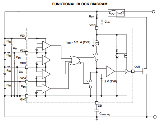
components

Design Notes

  • Place the IC close to the battery cells to minimize sensing errors due to trace resistance
  • Select appropriate external delay capacitor to set accurate overvoltage detection timing
  • Ensure proper grounding to improve noise immunity and ripple rejection
  • Consider thermal conditions in tightly packed battery modules
  • Use with primary protection IC for redundant safety architecture

How to Choose This Part

  • Select based on required overvoltage threshold (4.45V per cell for BQ29412)
  • Suitable for designs requiring secondary independent protection
  • Choose when high accuracy and stability under ripple conditions are critical
  • Ideal for multi-cell lithium-ion battery safety applications

Applications

  • Notebook computers
  • Portable instrumentation
  • Battery-powered portable equipment
  • Lithium-ion battery packs

Other data sheets are available within the file:

BQ29410, BQ29410DCT3R, BQ29410DCT3RE6, BQ29410DCTR, BQ29410DCTRG4


BQ29412 Datasheet PDF Download


BQ29412 pdf

AWS5506S14 Datasheet – SPDT Reflective Switch ( PDF )

Part Number: AWS5506S14

Function: GaAs IC SPDT Reflective Switch Positive Control DC-2.5 GHz

Package: SOT-6 Type

Manufacturer: ANADIGICS

Pinouts:

AWS5506S14 datasheet


Description

AWS5506S14 is a Single-Pole Double-Throw (SPDT) RF switch implemented using GaAs MMIC technology, designed for low insertion loss, compact size, and low power consumption. It is widely used in RF signal routing for wireless communication systems, especially in dual-band and multi-mode applications.

Features

  • SPDT (Single Pole Double Throw) RF switch
  • Low insertion loss: ~0.4 dB @ 0.9 GHz
  • Wideband RF performance (suitable for sub-GHz to GHz range)
  • Complementary positive control voltage (0 / +3V to 0 / +5V)
  • Supply voltage: +3V to +5V
  • Low DC power consumption
  • High isolation between ports (typical for GaAs switches)
  • Ultra-miniature SOT-6 package

Functional Description

  • Routes an RF signal from a common port to one of two selectable output ports
  • Control voltage determines signal path (RF1 ↔ RF2 or RF1 ↔ RF3)
  • GaAs FET structure enables low loss and high-frequency operation
  • Designed for minimal signal distortion and high linearity

Control Interface

  • Complementary control inputs allow easy logic interfacing
  • Compatible with standard CMOS/TTL control levels (3V / 5V systems)
  • Low control current requirement

Design Notes

  • Ensure proper 50Ω impedance matching on RF traces
  • Minimize PCB trace length to reduce insertion loss and reflections
  • Use RF layout best practices (ground plane, via stitching)
  • Decouple supply pin with RF-grade capacitors
  • Avoid exceeding maximum RF input power levels

How to Choose This RF Switch

  • Select based on frequency range and insertion loss requirements
  • Ensure isolation meets system-level RF performance targets
  • Verify control voltage compatibility with system logic
  • Consider package size for compact RF module designs

Typical Applications

  • RF signal routing in wireless systems
  • Dual-band / multi-band mobile handsets
  • RF front-end modules (FEM)
  • Switching between filters or amplifiers
  • Frequency synthesizers and signal chains

Alternative / Equivalent Products

  • Skyworks SKY13317 (RF switch alternative)
  • Peregrine PE4259 (higher performance RF switch)
  • HMC series RF switches (Analog Devices)
  • MASW series (MACOM RF switches)

Other data sheets are available within the file: AWS5506

AWS5506S14 Datasheet PDF Download


AWS5506S14 pdf