The L298 is a dual full-bridge (H-bridge) motor driver IC designed for driving inductive loads such as DC motors, stepper motors, relays, and solenoids.
Function: Dual Full-Bridge Driver
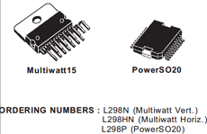
Package: Multiwatt15, Power-SO20 Pin Type
Manufacturer: STMicroelectronics
Image
Description
The L298 is an integrated monolithic circuit in a 15-lead Multiwatt and PowerSO20 packages. It is a high voltage, high current dual full-bridge driver designed to accept standard TTL logic levels and drive inductive loads such as relays, solenoids, DC and stepping motors. Two enable inputs are provided to enableor disable the device independently of the input signals.
The emitters of the lower transistors of each bridge are connected together and the corresponding external terminal can be used for the connection of an external sensing resistor. An additional supply input is provided so that the logic works at a lower voltage.
Features
- Wide operating supply voltage up to 46V
- Total DC current up to 4A (2A per channel typical)
- Low saturation voltage for improved efficiency (for BJT-based driver)
- Built-in overtemperature protection
- TTL-compatible logic inputs
- High noise immunity (logic “0” up to 1.5V)
- Independent enable control for each bridge
Pinouts

Functional Overview
- Contains two independent full H-bridge drivers
- Each bridge can drive one DC motor or one winding of a stepper motor
- Enable pins allow independent control of each bridge
- Separate logic and power supply pins improve noise immunity and flexibility
- External current sensing via emitter pins enables current monitoring/control
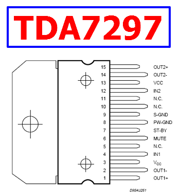
Pin Configuration (Multiwatt15 – Conceptual)
- IN1, IN2 → Control inputs for Bridge A
- IN3, IN4 → Control inputs for Bridge B
- ENA, ENB → Enable pins for each bridge
- OUT1, OUT2 → Outputs for Motor A
- OUT3, OUT4 → Outputs for Motor B
- SENSE A, SENSE B → Current sensing pins
- VS → Motor supply voltage
- VSS → Logic supply (typically 5V)
- GND → Ground
Typical Circuit Usage
- Bidirectional DC motor control (forward/reverse)
- Stepper motor driver (full-step or half-step control)
- Relay or solenoid driver arrays
- Robotics motor control systems
How to Choose This Part
- Use when operating voltage is high (up to ~46V) and current ≤2A per channel
- Suitable when robustness is more important than efficiency
- Good for legacy or educational designs due to simplicity
- Not ideal for battery-powered systems due to conduction losses
- Consider MOSFET-based drivers for higher efficiency designs
Applications
- DC motor drivers
- Stepper motor control systems
- Industrial automation
- Robotics and mechatronics
- Embedded control systems
Alternative / Equivalent Products
- L293D (lower current alternative with integrated diodes)
- TB6612FNG (MOSFET-based efficient driver)
- DRV8833 (low-voltage motor driver)
- VNH2SP30 (high-current integrated driver)
- MC33886 (automotive-grade driver)
Other data sheets are available within the file: L298N, L298HN, L298P
L298 Datasheet PDF Download