Part Number: TPS630250
Function: High Current, High Efficiency Single Inductor Buck-Boost Converter
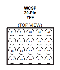
Package: 20-pin WCSP package measuring 1.766 mm x 2.086mm.
Manufacturer: Texas Instruments
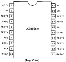
Pinouts:

Description
The TPS63025 are high efficiency, low quiescent current buck-boost converters suitable for application where the input voltage is higher or lower than the output. Output currents can go as high as 2A in boost mode and as high as 4A in buck mode. The maximum average current in the switches is limited to a typical value of 4A.
The TPS63025 regulates the output voltage over the complete input voltage range by automatically switching between buck or boost mode depending on the input voltage ensuring a seamless transition between modes.
The maximum average current in the switches is limited to a typical value of 4 A. The TPS63025x regulates the output voltage over the complete input voltage range by automatically switching between buck or boost mode depending on the input voltage ensuring a seamless transition between modes. The buck-boost converter is based on a fixed frequency, pulse-width-modulation (PWM) controller using synchronous rectification to obtain highest efficiency. At low load currents, the converter enters Power Save Mode to maintain high efficiency over the complete load current range. There is a PFM/PWM pin that allows the user to choose between automatic PFM/PWM mode operation and forced PWM operation. During PWM mode a fixed-frequency of typically 2.5 MHz is used. The output voltage is programmable using an external resistor divider, or is fixed internally on the chip. The converter can be disabled to minimize battery drain. During shutdown, the load is disconnected from the battery. The device is packaged in a 20-pin WCSP package measuring 1.766 mm × 2.086mm and 14-pin HotRod package measuring 2.5 mm × 3mm.
TPS630250 Circuit
Features
1. 2.5MHz Typical Switching Frequency
2. 35-µA Operating Quiescent Current
3. Integrated Soft Start
4. Power Save Mode
5. True Shutdown Function
TPS630250 Datasheet PDF Download

Official Site : https://www.ti.com/product/tps630250
Other data sheets are available within the file:
TPS630250, TPS630250YFFR, TPS630250YFFT, TPS630251, TPS630251YFFR