AD5735 Datasheet PDF – 12-Bit, Voltage Output DAC

Part Number: AD5735

Function: Quad-Channel, 12-Bit, Serial Input, 4 mA to 20 mA and Voltage Output DAC

Package: PLCC 64 Pin Type

Manufacturer: Analog Devices

Pinouts:

AD5735 datasheet


Description

The AD5735 is a quad-channel voltage and current output DAC that operates with a power supply range from −26.4 V to +33 V. On-chip dynamic power control minimizes package power dissipation in current mode. This reduced power dissipation is achieved by regulating the voltage on the output driver from7.4 V to 29.5 V using a dc-to-dc boost converter optimized for minimum on-chip power dissipation. The AD5735 uses a versatile 3-wire serial interface that operates at clock rates of up to 30 MHz and is compatible with standard SPI, QSPI™, MICROWIRE®, DSP, and microcontroller interface standards. The serial interface also features optional CRC-8 packet error checking, as well as a watchdog timer that monitors activity on the interface.

Features

1. 12-bit resolution and monotonicity
2. Dynamic power control for thermal management
3. Current and voltage output pins connectable to a single terminal
4. Current output ranges: 0 mA to 20 mA, 4 mA to 20 mA, and 0 mA to 24 mA
5. ±0.1% total unadjusted error (TUE) maximum
6. Voltage output ranges (with 20% overrange): 0 V to 5 V, 0 V to 10 V, ±5 V, and ±10 V
7. ±0.09% total unadjusted error (TUE) maximum
8. User-programmable offset and gain
9. On-chip diagnostics
10. On-chip reference: ±10 ppm/°C maximum −40°C to +105°C temperature range

Applications

1. Process control
2. Actuator control
3. PLCs

Other data sheets are available within the file: AD5735ACPZ,  AD5735ACPZ-REEL7

AD5735 Datasheet PDF Download


AD5735 pdf

GC7137A Datasheet – Display A/D Converter ( PDF )

Part Number: GC7137A

Function: Three half-LED Display A/D converter

Package: DIP, SOP 24 Pin Type

Manufacturer: Unspecified

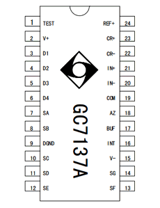
Pinouts:

GC7137A datasheet


Description

The GC7137A is a high performance, low-cost three and a half A/D converter circuit. It contains seven sections of the translation Code reader, scan display drivers, reference sources and clock system that can directly drive LED display characters.

The device be a good combination with high precision, versatility and low cost applications together, it has less than 10μV The auto zero function, zero drift of less than 1μV / ℃, lower than the input current 10pA, the polarity switching error is less than A word. GC7137 integrated differential input and differential reference source in a variety of systems are very easy to use. It can be widely For a variety of single-chip measurement unit and display meter.

Application Circuits :

components

Features

1. To ensure zero-level input, the readings of each range are zero.

2. Chip built-in frequency calibrated clock oscillator

3. True differential input and differential reference source

4. Single power supply 5V or external positive and negative dual power supply

5. Very low noise (less than 15µVp-p)

6. Display scan drive, no external components required

7. Low power consumption (typically less than 10mW)

8. Built-in precision bandgap reference source

Other data sheets are available within the file: GC7137


GC7137A Datasheet PDF Download


GC7137A pdf