FZH111A Datasheet PDF – Quad 2-input NAND Gate – Siemens

Part Number: FZH111A

Function: Quad 2-input NAND Gate

Package: DIP 16P

Manufacturer: Siemens AG

Image :
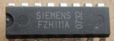
FZH111A

Description

The chips used DTL (Diode-Transistor Logic) which was a predessesor of of the TTL (Transistor-Transistor-Logic) manufactured in the late 60s. If neccesary I could provide basic data and pinout from an old Valvo databook but it might take some days to find it.

A NAND gate is a digital logic gate that implements the Boolean function NOT-AND, which is the inverse of an AND gate. The output of a NAND gate is ‘0’ only if all of its inputs are ‘1’, and it produces a ‘1’ in all other cases. In other words, if one or more inputs are ‘0’, the output will be ‘1’. NAND gates are widely used in digital circuits due to their versatility, as they can be used to implement any other type of logic gate by connecting them in a certain configuration. NAND gates are considered to be “universal gates” because they can be used to perform any logical operation by combining them in the right way.

Pinout

FZH111A pinout

FZH111A datasheet

Reference page :

1. https://www.eng-tips.com/viewthread.cfm?qid=59163

2. http://www.radiomuseum.org/tubes/tube_fzh111.html

FZH111A Datasheet PDF

Posts related to ‘ NAND Gate ‘

Part number Description
SN74LS00 Quad 2-input NAND gate
74LS20 Dual 4-Input Positive-NAND Gate – TI
74HC00 Quad 2-input NAND gate – Philips
74HC10 Triple 3-input NAND gate
HD74LS00 HD74LS00 – Quadruple 2-Input NAND Gates
SN74LS00 Quad NAND GATE – ON Semiconductor
5410 Triple 3-Input NAND Gates
7401 Quad 2-Input NAND Gate
5400 5400 – Quad 2-Input NAND Gates
7410 7410 – Triple 3-input NAND gate


OR2C26A Datasheet PDF – Field-Programmable Gate Array

Part Number: OR2C26A

Function: ORCA Feild-Programmable Gate Array. Voltage 5.0 V.

Package: 208, 240 SQFP, 304, 432 EBGA Pin Type

Manufacturer: Agere ( LSI Corporation )

Images:

OR2C26A datasheet


Description

The OR2C26A is Feild-Programmable Gate Arrays.

The ORCA Series 2 series of SRAM-based FPGAs are an enhanced version of the ATT2C/2T architecture. The latest ORCA series includes patented architectural enhancements that make functions faster and easier to design while conserving the use of PLCs and routing resources. The Series 2 devices can be used as drop-in replace ments for the ATT2Cxx/ATT2Txx series, respectively, and they are also bit stream compatible with each other.

The PLC architecture provides a balanced mix of logic and routing that allows a higher utilized gate/PFU than alternative architectures. The routing resources carry logic signals between PFUs and I/O pads. The routing in the PLC is symmetrical about the horizontal and vertical axes. This improves routability by allowing a bus of signals to be routed into the PLC from any direction.

What is FPGA?

FPGAs consist of a grid of configurable logic blocks (CLBs), which can be programmed to perform a variety of digital logic functions. These logic blocks can be interconnected using programmable routing resources, which allow designers to create custom digital circuits with high levels of flexibility and functionality.

FPGAs are programmed using hardware description languages (HDLs), such as Verilog or VHDL, which allow designers to specify the behavior of the digital circuit in a high-level language. The HDL code is then compiled into a configuration file, which is loaded onto the FPGA to configure the logic blocks and interconnects.

Features

1. Eight 3-state buffers per PFU for on-chip bus structures
2. High-performance, cost-effective, low-power 0.35 μm CMOS technology (OR2CxxA),
3. Full PCI bus compliance for all devices


Other data sheets are available within the file:

OR2C04A, OR2C06A, OR2C08A, OR2C10A, OR2C12A,
OR2C15A, OR2C40A, OR2C12A-4S240

OR2C26A Datasheet PDF Download


OR2C26A pdf