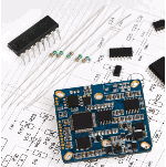
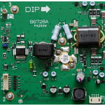
This post explains for the DC/DC Converter. A PWM (Pulse-Width Modulation) buck DC/DC converter, often referred to simply as a “buck converter,” is a type of power converter or voltage regulator used in electronics to step down voltage levels efficiently.
The Part Number is AC1501.
The Package is TO-220-5L Type.
The function of this semiconductor is PWM Buck DC/DC Converter.
Manufacturer: Anachip Corp.
Preview images :
1 page

Description
The AP1501 series are monolithic IC that design for a step-down DC/DC converter, and own the ability of driving a 3A load without additional transistor component. Due to reducing the number of external component, the board space can be saved easily.
The external shutdown function can be controlled by logic level and then come into standby mode.
The internal compensation makes feedback control have good line and load regulation without external design. Regarding protected function, thermal shutdown is to prevent over temperature operating from damage, and current limit is against over current operating of the output switch.
1. Voltage Regulation: Buck converters provide a stable and regulated output voltage even when the input voltage varies. This is essential for ensuring consistent power to sensitive electronic components.
2. PWM Control: Pulse-width modulation control allows for precise and flexible regulation of the output voltage. It can be adjusted to meet specific voltage requirements.
Features
1. 150Khz +15% fixed switching frequency
2. Voltage mode non-synchronous PWM control
3. Thermal-shutdown and current-limit protection
4. ON/OFF shutdown control input
5. Operating voltage can be up to 40V
6. Output load current: 3A
Block Diagram

Applications
1. Simple High-efficiency step-down regulator
2. On-card switching regulators
3. Positive to negative converter
AC1501 PDF Datasheet