Part Number: RJP63F3DPP-M0
Function: 630V, 40A, N-Channel IGBT
Package: TO-220FL Type
Manufacturer: Renesas
Images:
Description
RJP63F3DPP-M0 is 630V, Silicon N Channel IGBT.
IGBT stands for Insulated-Gate Bipolar Transistor. It is a type of power semiconductor device that combines the advantages of bipolar transistors (high voltage and current handling capability) and field-effect transistors (fast switching and low on-state resistance).
They are also used in applications where high voltage and high current are required, such as in welding equipment and induction heating.
An IGBT consists of a P-N-P-N structure with an insulated gate, which is used to control the flow of current between the emitter and collector terminals. When a positive voltage is applied to the gate terminal, it creates a conducting channel between the emitter and collector, allowing current to flow.
When the gate voltage is removed, the channel is turned off, and the IGBT becomes an open switch.
These advantages include high voltage and current handling capability, fast switching speed, low switching losses, and low on-state resistance.
Applications:
1. High Speed Power Switching
Features
1. Trench gate and thin wafer technology (G6H series)
2. Low collector to emitter saturation voltage VCE(sat) = 1.7 V typ
3. High speed switching tf = 100 ns typ
4. Low leak current ICES = 1 μA max
5. Isolated package TO-220FL
Package code :
PRSS0003AF-A) (Package name: TO-220FL) C G 1. Gate 2. Collector 3. Emitter

Absolute Maximum Ratings (Ta = 25°C) :
1. Collector to Emitter Voltage: Vces = 630 V
2. Gate to Emitter Voltage: VGes = ± 30 V
3. Collector Current: Ic = 40 A
4. Collector dissipation: Pc = 30 W
5. Operating Junction Temperature: Tch = -55 to +150 °C
6. Storage temperature: Tstg = -55 to +150 °C
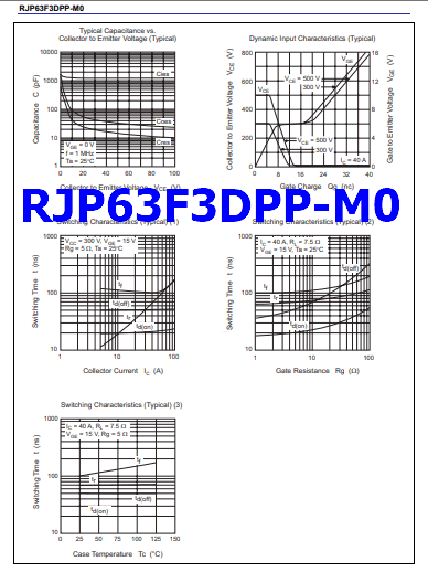
Notes: 3. Pulse test. R07DS0321EJ0200 Rev.2.00 May 26, 2011 Page 2 of 6 RJP63F3DPP-M0 Preliminary Main Characteristics Maximum Safe Operation Area 1000 100 10 PW Typical Output Characteristics (1) Pulse Test Ta 4 6 8 10 Collector to Emitter Voltage VCE (V) Gate to Emitter Voltage VGE (V) Collector to Emitter Saturation Voltage vs. Gate to Emitter Voltage (Typical) Collector […]
RJP63F3DPP-M0 PDF Datasheet