MPC9449 Datasheet – Clock Fanout Buffer ( PDF )

Part Number: MPC9449

Function: 3.3 V/2.5 V 1:15 PECL/LVCMOS Clock Fanout Buffer

Package: 52-Lead Type

Manufacturer: Motorola, Renesas

Image:
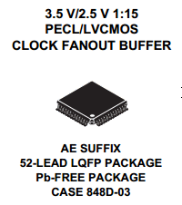
MPC9449 datasheet


Description

The MPC9449 is a 3.3 V or 2.5 V compatible, 1:15 clock fanout buffer targeted for high performance clock tree applications. With output frequencies up to 200 MHz and output skews less than 200 ps the device meets the needs of the most demanding clock applications.

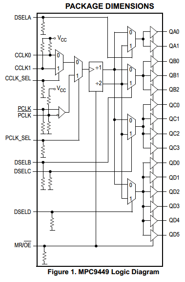
Block Diagram
components

The MPC9449 is specifically designed to distribute LVCMOS compatible clock signals up to a frequency of 200 MHz. The device has 15 identical outputs, organized in four output banks. Each output bank provides a retimed or frequency divided copy of the input signal with a near zero skew. The output buffer supports driving of 50Ω terminated transmission lines on the incident edge: each output is capable of driving either one parallel terminated or two series terminated transmission lines.

Pinout
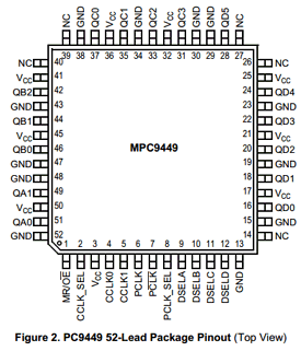
components

Features

• 15 LVCMOS compatible clock outputs
• Two selectable LVCMOS and one differential LVPECL compatible clock inputs
• Selectable output frequency divider (divide-by-one and divide-by-two)
• Maximum clock frequency of 200 MHz
• Maximum clock skew of 200 ps
• High-impedance output control

Other data sheets are available within the file: MPC-9449

MPC9449 Datasheet PDF Download


MPC9449 pdf

Related articles across the web

DS1307 Datasheet – 64 x 8, Serial, Real-Time Clock – Maxim

Part Number: DS1307

Function: 64 x 8, Serial, I2C Real-Time Clock

Package: 8-Pin DIP, 8-Pin SO Type

Manufacturer: Maxim Integrated

Image

ds1307-real-time-clock
GENERAL Description

The DS1307 serial real-time clock (RTC) is a low power, full binary-coded decimal (BCD) clock/calendar plus 56 bytes of NV SRAM. Address and data are transferred serially through an I2C, bidirectional bus.

The clock/calendar provides seconds, minutes, hours, day, date, month, and year information. The end of the month date is automatically adjusted for months with fewer than 31 days, including corrections for leap year. The clock operates in either the 24-hour or 12-hour format with AM/PM indicator. The DS1307 has a built-in power-sense circuit that detects power failures and automatically switches to the backup supply.

Timekeeping operation continues while the part operates from the backup supply.


Pinouts:

DS1307 datasheet


Features

1. Real-Time Clock (RTC) Counts Seconds, Minutes, Hours, Date of the Month, Month, Day of the week, and Year with Leap-Year Compensation Valid Up to 2100
2. 56-Byte, Battery-Backed, General-Purpose RAM with Unlimited Writes
3. I2C Serial Interface
4. Programmable Square-Wave Output Signal 
5. Automatic Power-Fail Detect and Switch Circuitry
6. Consumes Less than 500nA in Battery-Backup Mode with Oscillator Running
7. Optional Industrial Temperature Range: -40°C to +85°C
8. Available in 8-Pin Plastic DIP or SO
9. Underwriters Laboratories (UL) Recognized


Official HomePage : https://www.maximintegrated.com/en/products/digital/real-time-clocks/DS1307.html


DS1307 Datasheet

DS1307 pdf

Other data sheets are available within the file: DS1307+, DS1307N+, DS1307Z+, DS1307Z+T&R

Related articles across the web