SD6832 Datasheet PDF – Current Mode PWM+PFM Controller

Part Number: SD6832

Function: Current Mode PWM+PFM Controller With Built-in High-voltage MOSFET

Package:  DIP 8 Pin Type

Manufacturer: Hangzhou Silan Microelectronics

Images:
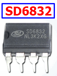
SD6832 datasheet

Description

SD6832 is current mode PWM+PFM controller with built-in high-voltage MOSFET used for SMPS. It features low standby power and low start current. In standby mode, the circuit enters burst mode to reduce the standby power dissipation. The switch frequency is 25~67KHz decided by the load with jitter frequency for low EMI. Built-in peak current compensation circuit makes the limit peak current stable even with different input AC voltage. Maximum peak current compensation during power-on reduces pressure on transformer to avoid saturation, the peak current compensation will decrease for balance after power-on. Limit output current can be adjusted through the resistor connected to CS.

Pinout:

SD6832 pinout controller

Features

1. Energy Star 2.0 standard
2. Lower start-up current (3mA)
3. Various switching frequency following load for the high efficiency
4. Frequency jitter for low EMI
5. Overvoltage, primary winding overcurrent, overload and over temperature protections.
6. External peak current sense resistor
7. Undervoltage lockout
8. Built-in high voltage MOSFET
9. Auto restart mode

Applications

1. Charger
2. Adaptor
3. STB Power

Other data sheets are available within the file: D6832

SD6832 Datasheet PDF


SD6832 pdf

Related articles across the web

S2R72V27 Datasheet – USB Host/Device Controller – EPSON

Part Number: S2R72V27

Function: USB Host/Device Controller

Package:  QFP14-80

Manufacturer: EPSON

Image

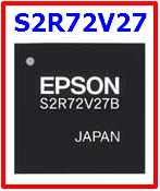
S2R72V27 USB Controller

Description

The S2R72V27 is a USB host/device controller LSI that supports the USB 2.0 high-speed mode. A single USB port can be operated as a USB host or USB device depending on how control is switched. This LSI maintains high compatibility with the S2R72V17 but includes additional functions such as support for USB host isochronous transfers. This Device is also compatible with S2R72V27 at it’s function.

Pinout

S2R72V27 datasheet pinout


Features

1. Supports HS (480 Mbps), FS (12 Mbps), and LS (1.5 Mbps) transfer
2. Built-in pull-down resistor for downstream ports (no external circuit required)
3. Built-in HS termination (no external circuit required)
4. Supports control, bulk, interrupt, and isochronous transfers
5. Supports HS (480 Mbps) and FS (12 Mbps) transfer
6. Built-in FS/HS termination (no external circuit required)
7. VBUS 5V I/F (requires external protective circuit)
8. Supports control, bulk, interrupt, and isochronous transfers

The sequence of steps for turning the power supplies on and off are described below. This LSI cannot be operated with only the LVDD or CVDD power supplies turned on or off. The HVDD can be turned off if the LVDD or CVDD power supplies are on. The synchronous register cannot be accessed while HVDD is off, since the PLL does not operate. Also, the following restrictions apply to the sequence for turning the CVDD/HVDD I/O power supplies and LVDD internal power supply on or off. There are no restrictions on the sequence for turning the CVDD and HVDD power supplies on or off.


S2R72V27 Datasheet


Related articles across the web