TL431 Datasheet PDF – Shunt Regulator Diode – Motorola

Part Number: TL431

Function: Programmable Precision References

Package: TO 92, DIP 8 Pin, DIP 8 Pin Type

Manufacturer: Motorola

Images and Pinouts:
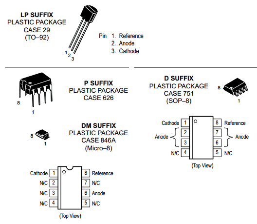
TL431 Datasheet

Description

The TL431, TL431A, TL431B integrated circuits are three–terminal programmable shunt regulator diodes. These monolithic IC voltage references operate as a low temperature coefficient zener which is programmable from V refto 36 V with two external resistors. These devices exhibit a wide operating current range of 1.0 mA to 100 mA with a typical dynamic impedance of 0.22 Ω. The characteristics of these references make them excellent replacements for zener diodes in many applications such as digital voltmeters, power supplies, and op amp circuitry. The 2.5 V reference makes it convenient to obtain a stable reference from 5.0 V logic supplies, and since the TL431, A, B operates as a shunt regulator, it can be used as either a positive or negative voltage reference.

Features

1. Programmable Output Voltage to 36 V

2. Voltage Reference Tolerance: ±0.4%, Typ @ 25°C (TL431B)

3. Low Dynamic Output Impedance, 0.22 ΩTypical

4. Sink Current Capability of 1.0 mA to 100 mA

5. Equivalent Full–Range Temperature Coefficient of 50 ppm/°C Typical

6. Temperature Compensated for Operation over Full Rated Operating Temperature Range

7. Low Output Noise Voltage

Block Diagram
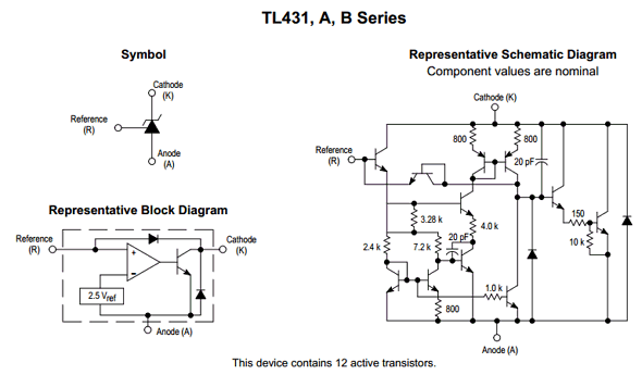
TL431 Diagram

Other data sheets are available within the file: TL431CP, TL431CD, TL431IP, TL431ID

TL431 Datasheet PDF

 pdf


Related articles across the web

DRD5940H55 Datasheet PDF – 5500V, 5940A, Rectifier Diode

Part Number: DRD5940H55

Function : Rectifier Diode ( VRRM 5500V, IF(AV) 5940A )

Package outline type code: H

Manufacturer: DYNEX ( www.dynexsemi.com )

Image
drd5940h55-rectifier-diode

Description

The DRD5940H55 is 5500V, 5940A, Diode.

A recovery diode is a type of diode that is used in power electronics circuits to control the flyback voltage that is generated when a switch (such as a transistor or thyristor) is turned off. The flyback voltage is a high-frequency, high-voltage spike that occurs when the energy stored in the inductive load is rapidly dissipated as the switch is turned off.

The recovery diode is connected in parallel with the inductive load and is designed to conduct current as soon as the switch is turned off, effectively short-circuiting the flyback voltage and preventing it from damaging the switch or other components in the circuit. The diode will then cease conducting as the flyback voltage decays, allowing the switch to turn on again.

Features

1. Double Side Cooling
2. High Surge Capability


KEY PARAMETERS

1. Peak repetitive peak reverse voltage : VRRM = 5500V
2. Average forward current : IF(AV) 5940A
3. Peak forward current : IFSM = 93600A


Voltage Ratings

drd5940h55-datasheet-pinout

Official Homepage: https://www.dynexsemi.com/

Other data sheets are available within the file:

DRD5940H52, DRD5940H50, DRD5940H48, DRD5940H46

DRD5940H55 Datasheet PDF


Related articles across the web