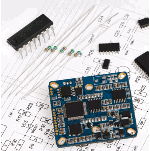
LM3915 Datasheet PDF – Backlight LED Driver, DIP 18

Part Number: LM3915, LM3915N

Function : Dot / Bar Display Driver

Package: DIP 18 Pin type

Manufacturer: National Semiconductor, TI

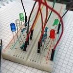
Image
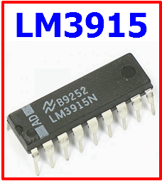
lm3915-led-driver

Description

The LM3915 is a monolithic integrated circuit that senses analog voltage levels and drives ten LEDs, LCDs or vacuum fluorescent displays, providing a logarithmic 3 dB/step analog display. One pin changes the display from a bar graph to a moving dot display. LED current drive is regulated and programmable, eliminating the need for current limiting resistors. The whole display system can operate from a single supply as low as 3V or as high as 25V. The IC contains an adjustable voltage reference and an accurate ten-step voltage divider. The high-impedance input buffer accepts signals down to ground and up to within 1.5V of the positive supply. Further, it needs no protection against inputs of ±35V. The input buffer drives 10 individual comparators referenced to the precision divider. Accuracy is typically better than 1 dB.

Pinout
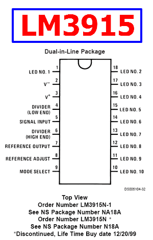
lm3915-datasheet-pinout


Features

1. 3 dB/step, 30 dB range

2. Drives LEDs, LCDs, or vacuum fluorescents

3. Bar or dot display mode externally selectable by user

4. Expandable to displays of 90 dB

5. Internal voltage reference from 1.2V to 12V

6. Operates with single supply of 3V to 25V

7. Inputs operate down to ground

8. Output current programmable from 1 mA to 30 mA


Typical Applications
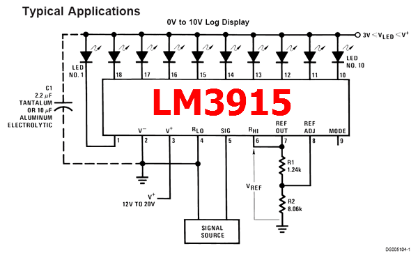
lm3915-application-circuit


Reference Site: https://en.wikipedia.org/wiki/LM3914


LM3915 Datasheet


Related articles across the web

IR2110 Datasheet – High and Low Side Driver – IR

Part Number: IR2110, IR2113

Function: High and Low Side Driver

Package: DIP 14 Pin type

Manufacturer: International Rectifier, ( https://www.infineon.com/ ), infineon

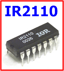
Image :

ir2110-side-driver

Description

The IR2110 / IR2113 are high voltage, high speed power MOSFET and IGBT drivers with independent high and low side referenced output channels. Proprietary HVIC and latch immune CMOS technologies enable ruggedized monolithic construction. Logic inputs are compatible with standard CMOS or LSTTL output, down to 3.3V logic. The output drivers feature a high pulse current buffer stage designed for minimum driver cross-conduction. Propagation delays are matched to simplify use in high frequency applications. The floating channel can be used to drive an N-channel power MOSFET or IGBT in the high side configuration which operates up to 500 or 600 volts.


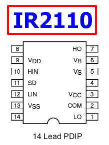
Pinout

ir2110-datasheet-pinout


Features

1. Floating channel designed for bootstrap operation Fully operational to +500V or +600V Tolerant to negative transient voltage dV/dt immune

2. Gate drive supply range from 10 to 20V

3. Undervoltage lockout for both channels

4. 3.3V logic compatible Separate logic supply range from 3.3V to 20V Logic and power ground ±5V offset

5. CMOS Schmitt-triggered inputs with pull-down

6. Cycle by cycle edge-triggered shutdown logic

7. Matched propagation delay for both channels

8. Outputs in phase with inputs

Reference Site

http://tahmidmc.blogspot.kr/2013/01/using-high-low-side-driver-ir2110-with.html


IR2110 Datasheet

IR2110 pdf


Other data sheets are available within the file: 2101, IR2101, IR2101S, IR2101SPBF, IR2110

Related articles across the web