IMX29F002 PDF Datasheet – 2M-BIT [256K x 8] CMOS Flash Memory

Part Number: IMX29F002

Function: 2M-BIT [256K x 8] CMOS Flash Memory

Package: DIP, PLCC, TSOP 32 Pin Type

Manufacturer: Macronix International

Images:IMX29F002 pdf memory

Description

The MX29F002, MX29F002T, MX29F002B is a 2-mega bit Flash memory organized as 256K bytes of 8 bits only. MXIC’s Flash memories offer the most cost-effective and reliable read/write nonvolatile random access memory. The MX29F002T/B is packaged in 32-pin PDIP,PLCC and 32-pin TSOP(I). It is designed to be reprogrammed and erased in-system or in-standard EPROM programmers.

CMOS (Complementary Metal-Oxide-Semiconductor) flash memory is a type of non-volatile memory technology used for data storage in a wide range of electronic devices, including USB drives, memory cards, solid-state drives (SSDs), and embedded systems. It offers advantages such as fast read and write speeds, low power consumption, and robust data retention even when the power supply is removed.

Features

• 262,144x 8 only

• Fast access time: 55/70/90/120ns

• Low power consumption
– 30mA maximum active current(5MHz)
– 1uA typical standby current

• Programming and erasing voltage 5V ± 10%

• Command register architecture

– Byte Programming (7us typical)

Pinouts:

IMX29F002 pinout datasheet

IMX29F002 PDF Datasheet

Related articles across the web

30J324 PDF – 600V, 30A, IGBT, GT30J324 ( Datasheet )

Part Number: 30J324, GT30J324

Function: 600V, 30A, N-Channel, IGBT ( Insulated Gate Bipolar Transistor )

Package: TO-3P Type

Manufacturer: Toshiba Semiconductor

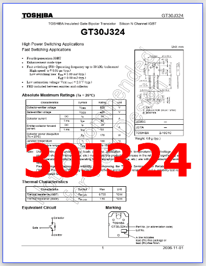
Images:30J324 pdf pinout

Description

The 30J324 is 600V, 30A, Silicon N Channel IGBT. IGBT stands for Insulated-Gate Bipolar Transistor. It is a type of power semiconductor device that combines the advantages of bipolar transistors (high voltage and current handling capability) and field-effect transistors (fast switching and low on-state resistance).

They are also used in applications where high voltage and high current are required, such as in welding equipment and induction heating.

An IGBT consists of a P-N-P-N structure with an insulated gate, which is used to control the flow of current between the emitter and collector terminals. When a positive voltage is applied to the gate terminal, it creates a conducting channel between the emitter and collector, allowing current to flow.

When the gate voltage is removed, the channel is turned off, and the IGBT becomes an open switch.

Applications:

1. High Power Switching

2. Fast Switching

Features

1. The 4th generation

2. Enhancement-mode

3. Fast switching (FS): Operating frequency up to 50 kHz (reference)

(1) High speed: tf = 0.05 µs (typ.)
(2) Low switching loss: Eon = 1.00 mJ (typ.) : Eoff = 0.80 mJ (typ.)

4. Low saturation voltage: VCE (sat) = 2.0 V (typ.)

5. FRD included between emitter and collector

30J324 datasheet igbt

Absolute Maximum Ratings (Ta = 25°C)

1. Collector to emitter voltage: Vces = 600 V

2. Gate to emitter voltage: Vges = ± 20 V

3. Collector current : Ic = 30 A

4. Collector dissipation : Pc = 170 W

5. Junction temperature : Tj = 150 °C

6. Storage temperature: Tstg = -55 to +150 °C

30J324 PDF Datasheet