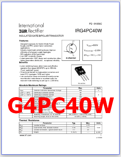
Part Number: G4PC40W, IRG4PC40W
Function: 600V, 40A, IGBT ( The IGBT is insulated-gate bipolar transistor. )
Package: TO-247AC type
Manufacturer: IRF
Description
THE G4PC40W IS INSULATED GATE BIPOLAR TRANSISTOR. IGBT stands for Insulated-Gate Bipolar Transistor. It is a type of power semiconductor device that combines the advantages of bipolar transistors (high voltage and current handling capability) and field-effect transistors (fast switching and low on-state resistance).
They are also used in applications where high voltage and high current are required, such as in welding equipment and induction heating.
An IGBT consists of a P-N-P-N structure with an insulated gate, which is used to control the flow of current between the emitter and collector terminals. When a positive voltage is applied to the gate terminal, it creates a conducting channel between the emitter and collector, allowing current to flow.
Features:
• Designed expressly for Switch-Mode Power Supply and PFC (power factor correction) applications
• Industry-benchmark switching losses improve efficiency of all power supply topologies
• 50% reduction of Eoff parameter
• Low IGBT conduction losses
• Latest-generation IGBT design and construction offers tighter parameters distribution, exceptional reliability VCES = 600V G E VCE(on) typ. = 2.05V @VGE = 15V, IC = 20A n-channel

Benefits:
• Lower switching losses allow more cost-effective operation than power MOSFETs up to 150 kHz (“hard switched” mode)
• Of particular benefit to single-ended converters and boost PFC topologies 150W and higher
• Low conduction losses and minimal minority-carrier recombination make these an excellent option for resonant mode switching as well (up to >>300 kHz) TO-247AC
Absolute Maximum Ratings (Tc = 25°C)
1. Collector-to-Emitter Breakdown Voltage : Vces = 600 V
2. Continuous Collector Current : 40 A
3. Pulsed Collector Current: Icm = 160 A
4. Maximum Power Dissipation : PD = 160 W
5. Channel temperature: Tch = 150 °C
6. Storage temperature: Tstg = -55 to +150 °C
G4PC40W PDF Datasheet