C2655 Transistor – 50V, 2A, NPN, Power Amplifier ( PDF )

This post explains for the transistor.

Part Number: C2655, 2SC2655

Function: 50V, 2A, Silicon NPN Transistor

Package: TO-92MOD Type

Manufacturer: Toshiba

See the preview image and the PDF file for more information.

C2655 transistor Image

C2655 transistor

Description

The C2655 is a medium-power NPN silicon transistor designed for both linear amplification and switching applications. It offers low saturation voltage, relatively fast switching characteristics, and moderate current capability, making it suitable for audio stages and general-purpose power control circuits.

Features

1. Low saturation voltage: VCE (sat) = 0.5 V (max) (IC = 1 A)

2. High collector power dissipation: PC = 900 mW

3. High-speed switching: tstg = 1.0 μs (typ.)

4. Complementary to 2SA1020.

C2655 Pinout
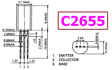
C2655 datasheet


Absolute maximum ratings ( Ta=25°C )

1. Collector to Base Voltage: Vcbo = 50 V

2. Collector to Emitter Voltage: Vceo = 50 V

3. Emitter to Base Voltage: Vebo = 5 V

4. Collector Current: Ic = 2A

5. Total Dissipation : Pc = 900 mW

6. Junction Temperature: Tj = 150°C

7. Storage Temperature: Tsg = -55 ~ +150°C

Design Notes (Critical Points)

  • Ensure adequate base drive for full saturation
  • Thermal dissipation is a major limitation (900mW max)
  • Use heat sinking or PCB copper area if operating near limits
  • Include flyback diode when driving inductive loads
  • Avoid operation near maximum ratings for reliability

Advantages vs MOSFET

  • Simpler drive requirements (no gate charge considerations)
  • Better linear behavior for analog amplification

Typical Applications

  • Audio power amplifier stages (driver/output stage)
  • Push-pull amplifier circuits
  • Relay drivers and inductive load switching
  • General-purpose power switching
  • Motor control (low power)

Alternative / Equivalent Products

  • 2SC2655 (standard naming variant)
  • BD139 (higher power capability)
  • 2N2222 (lower current applications)
  • 2SC1815 (signal-level use)

Other data sheets are available within the file: 2SC2655

C2655 Datasheet PDF Download

C2655 pdf

Related articles across the web

HIF3BA-XXX Datasheet – Ribbon Cable Connector ( PDF )

Part Number: HIF3BA-XXX

Function: Ribbon Cable connector Compliant with MIL Standard

Manufacturer: HIROSE ELECTRIC

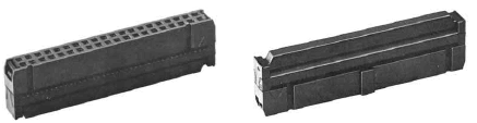
Image:

HIF3BA-XXX datasheet


Description

HIF3BA-XXX is a ribbon cable connector series from Hirose, designed in compliance with MIL standards for reliable board-to-cable interconnection. It is intended for use with flat ribbon cables (typically UL2651 AWG#28) and incorporates mechanical polarization features to prevent mis-insertion. The connector is widely used in industrial, instrumentation, and embedded systems requiring robust and repeatable connections.

1. Product Compliant with MIL Standard

HIF3B series has been developed as a product compliant with MIL

standard, and used for wide applications.

2. UL Approval Product

HIF3B series connectors are UL approved.

3. Mechanism to Prevent Mis-insertion

Features

  • MIL standard compliant ribbon cable connector
  • UL-approved product for safety and reliability
  • Supports UL2651 AWG#28 flat ribbon cable
  • 2.54 mm pitch (standard IDC spacing)
  • Multiple pin counts available (e.g., 6, 10, 14 positions)
  • IDC (Insulation Displacement Contact) termination for easy cable assembly
  • Reliable mechanical locking and alignment system

Mechanical Characteristics

Parameter Description
Pitch 2.54 mm
Cable Type Flat ribbon cable (UL2651, AWG#28)
Termination IDC (Insulation Displacement)
Mounting Cable mount (mates with PCB header)

Mis-insertion Prevention Mechanism

  • Guide-key system aligns connector with mating header
  • Polarizing key embedded in socket prevents incorrect orientation
  • Mechanical asymmetry ensures correct mating position

Compliance & Certification

  • MIL standard compliant design
  • UL approved for safety (file varies by model)

Design Notes

  • Ensure compatibility with matching Hirose HIF3B series pin headers
  • Use proper IDC crimping tool to ensure reliable termination
  • Maintain correct cable orientation to match polarization key
  • Verify pin count and pitch for system compatibility
  • Consider strain relief for high-vibration environments

How to Choose This Part

  • Select based on required number of positions (e.g., 6, 10, 14 pins)
  • Ensure compatibility with AWG#28 ribbon cable
  • Verify mating connector (header) type and pitch
  • Choose variants with locking features if vibration resistance is required

Typical Applications

  • Board-to-cable interconnections
  • Industrial control systems
  • Instrumentation and measurement equipment
  • Embedded systems and computing interfaces

Alternative / Equivalent Products

  • Hirose HIF3B header series
  • TE Connectivity IDC ribbon connectors
  • Amphenol FCI ribbon cable connectors
  • 3M IDC socket connectors

Other data sheets are available within the file:

HIF3BA- 6D-2.54R , HIF3BA-10D-2.54R , HIF3BA-14D-2.54R

HIF3BA-16D-2.54R , HIF3BA-20D-2.54R , HIF3BA-26D-2.54R

HIF3BA-30D-2.54R , HIF3BA-34D-2.54R , HIF3BA-40D-2.54R

HIF3BA-50D-2.54R , HIF3BB-50D-2.54R , HIF3BA-60D-2.54R

HIF3BB-60D-2.54R , HIF3BA-64D-2.54R , HIF3BB-64D-2.54R


HIF3BA-XXX Datasheet PDF Download


HIF3BA-XXX pdf