TLP651 Datasheet PDF – Photocoupler, DIP 8 – Toshiba

Part Number: TLP651

Function: Photocoupler GaA-As IRed & Photo−IC

Package: 11-10C4, DIP 8

Manufacturer: Toshiba

Image:
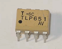
TLP651 datasheet

Description

TLP651 is a high-speed optocoupler from Toshiba that integrates an infrared LED and a photodiode-transistor detector in an 8-pin DIP package with 5000Vrms isolation capability. It provides fast switching performance with TTL-compatible output and includes an accessible base pin for improved analog operation and noise control. This device is widely used for signal isolation in digital logic, power supplies, and microprocessor interface circuits.

Features

  • High isolation voltage of 5000Vrms minimum
  • High-speed switching (tpHL ≈ 0.3µs, tpLH ≈ 0.5µs)
  • TTL-compatible output characteristics
  • Integrated photodiode-transistor detector
  • Base pin access for analog control and noise reduction
  • UL1577 and cUL certified isolation device
  • 8-pin DIP package for through-hole mounting

Pinout
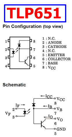
TLP651 pinout

Design Notes

  • Use the base pin connection to stabilize operation in analog or high-noise environments
  • Keep input LED drive current within recommended limits to ensure long-term reliability
  • Maintain proper creepage and clearance distances to preserve isolation performance
  • Decouple supply lines to reduce switching noise coupling into output stages
  • Select pull-up resistor values carefully to balance speed and power consumption

Typical Circuit Usage

  • Digital signal isolation between logic domains
  • Switching power supply feedback loops
  • Microprocessor and MCU interface isolation
  • Line receiver and communication isolation circuits

How to Choose This Part

  • Select for high-speed optocoupling with TTL-compatible outputs
  • Suitable for designs requiring high isolation voltage (5kVrms)
  • Use when analog control via base pin is beneficial
  • Consider TLP650 variant if base pin is not required

Applications

  • Digital logic ground isolation
  • Switching power supply control systems
  • Industrial control interfaces
  • Signal isolation in embedded systems

Alternative / Equivalent Products

  • TLP650 (no base pin version)
  • HCPL-2630
  • 6N137
  • ACPL-2631


TLP651 Datasheet PDF Download


TLP651 pdf

Other data sheets are available within the file:  TL-P651
PC817 Datasheet PDF – Photocoupler, DIP 4 – Sharp

A photocoupler, also known as an optocoupler or optoisolator, is an electronic component that is used to transfer electrical signals between two isolated circuits using light. It consists of an optically coupled pair, typically an LED (Light-Emitting Diode) on one side and a photodetector (such as a phototransistor or a photodiode) on the other side, enclosed in a single package.

Part Number: PC817

Function: General Purpose Photocoupler

Package: DIP 4pin

Manufacturer: Sharp Electronics

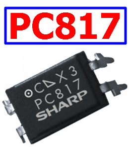
Image :

PC817 Photocoupler

Features

1. Double transfer mold package (Ideal for Flow Soldering)

2. High isolation voltage between input and output (Viso(rms) : 5kV)

3. High collector-emitter voltage(VCEO : 80V)

4. Current transfer ratio (CTR : MIN. 50% at IF=5 mA, VCE=5V)

5. RoHS directive compliant

Images:

PC817 Image


Description

The PC817 Series contains an IRED optically coupled to a phototransistor.

It is packaged in a 4pin DIP, available in wide-lead spacing option and SMT gullwing lead-form option.

Input-output isolation voltage(rms) is 5.0kV.

Collector-emitter voltage is 80V(*) and CTR is 50% to 600% at input current of 5mA.

Pinout:

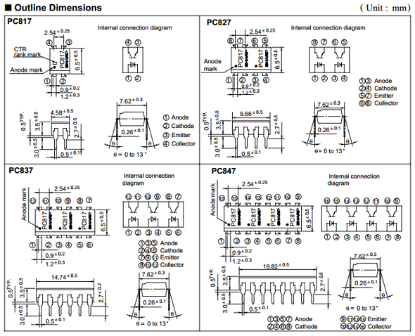
PC817 Datasheet Pinout

Compact Dual-in-line Package:

1. PC-817 : 1-channel type
2. PC817 : 2-channel type
3. PC817 : 3-channel type
4. PC817 : 4-channel type

PC827 Datasheet PDF, PC837, PC847

1. LED (Light-Emitting Diode): The input side of the photocoupler contains an LED that emits light when a current is applied to it. The light emission is typically in the infrared spectrum, but other wavelengths can also be used.

2. Photodetector: The output side of the photocoupler contains a photodetector (such as a phototransistor or photodiode) that detects the incoming light from the LED and generates a corresponding electrical signal.

3. Optically Transparent Barrier: Between the LED and the photodetector, there is an optically transparent barrier that isolates the input and output sides, preventing any direct electrical connection between them. This isolation provides electrical isolation between the two circuits.

Applications:

1. Programmable controllers

2. Facsimiles

3. Telephones

4.  I/O isolation for MCUs (Micro Controller Units)

5. Noise suppression in switching circuits

6. Signal transmission between circuits of different potentials and impedances

Download PC817 Datasheet PDF

PC817 pdf

Other data sheets are available within the file: PC827, PC837, PC847

Posts related to ‘ Photocoupler

Part number Description
TLP250 Photocoupler – Toshiba
TLP521 Photocoupler, Photo−Transistor
LTV817 1-Channel, Photocoupler
FL817 Phototransistor, Photocoupler
2561 Photocoupler ( PS2561 )
TLP280 Photocoupler, SOP 8 – Toshiba
6N137 Photocoupler – Everlight
PS2501-4 Multi Optocouler, Photocoupler
TLP421 Photocoupler – Toshiba
BP2832 SSOP, PhotoCoupler


Related articles across the web