A1707 PDF Datasheet – 50V, 3A, PNP Transistor – 2SA1707

This post describes for the Transistor.

The Part Number is 2SA1707, A1707.

The package is NMP type.

The function of this semiconductor is -50V, -3A, PNP Transistor.

The manufacturer of this part is Sanyo Semicon Device.

See the preview image and the PDF file for more information.

1 page
A1707 pdf pinout

Description

A1707 is -50V, -3A, PNP Epitaxial Planar Silicon Transistor.

Features

1. Adoption of FBET, MBIT processes.

2. Large current capacity, wide ASO.

3. Low collector-to-emitter saturation voltage.

4. Fast switching speed.


2 page
A1707 datasheet transistor

Absolute Maximum Ratings at Ta = 25°C

1. Collector-to-Base Voltage : VCBO = (–)60 V

2. Collector-to-Emitter Voltage : VCEO = (–)50 V

3. Emitter-to-Base Voltage : VEBO = (–)6 V

4. Collector Current : IC = (–)3 A

5. Collector Current (Pulse) : ICP (–) = 6 A

6. Collector Dissipation : PC = 1 W

7. Junction Temperature: Tj = 150


Applications:

1. High-Current Switching

A1707 Datasheet PDF

Posts related to ‘ PNP Transistor ‘

Part number Description
A1266 50V, 0.15A, PNP Transistor, 2SA1266
MPS2907ARLRE 60V, PNP Transistor
A1290 Silicon PNP Transistor, -60V, -7A
KTC9012 V cbo = -40V, PNP Transistor – KEC
BF-484 TO92, Vcbo = -250V, PNP Transistor
B778 120V, 10A, PNP Transistor, TO-3P ( PDF )
2SA1103 100V, 7A, PNP Transistor
A1850 120V, 200mA, PNP Transistor – Sanyo
XP0111M 50V, 100mA, PNP Transistor
B1548 60V, 3A, PNP Transistor – Panasonic


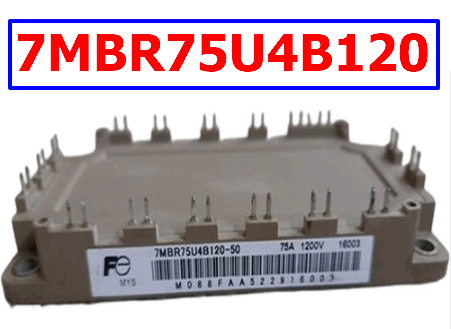
7MBR75U4B120 PDF Datasheet – 1200V, 75A, IGBT – Fuji

Part Number: 7MBR75U4B120

Function: 1200V, 75A, IGBT, Power Integrated Module

Package: Module Type

Manufacturer: Fuji Electric

Images:

7MBR75U4B120 datasheet pdf

Description

7MBR75U4B120 is 1200V, 75A, IGBT, Power Integrated Module.

IGBT stands for Insulated-Gate Bipolar Transistor. It is a type of power semiconductor device that combines the advantages of bipolar transistors (high voltage and current handling capability) and field-effect transistors (fast switching and low on-state resistance).

They are also used in applications where high voltage and high current are required, such as in welding equipment and induction heating.

An IGBT consists of a P-N-P-N structure with an insulated gate, which is used to control the flow of current between the emitter and collector terminals. When a positive voltage is applied to the gate terminal, it creates a conducting channel between the emitter and collector, allowing current to flow.

When the gate voltage is removed, the channel is turned off, and the IGBT becomes an open switch.

These advantages include high voltage and current handling capability, fast switching speed, low switching losses, and low on-state resistance.


Absolute Maximum Ratings (Ta = 25°C)

1. Collector to Emitter Voltage: Vces = 1200 V

2. Gate to Emitter Voltage: VGes = ± 20 V

3. Collector Current: Ic = 75 A

4. Collector power dissipation: Pc = 275 W

5. Junction Temperature: Tj = 150 °C

6. Storage temperature: Tstg = -40 to +125 °C


Block diagram

7MBR75U4B120 igbt fuji

7MBR75U4B120 Datasheet