36MT100 Didoe – Bridge Rectifier ( 1000V, 35A )

Part Number: 36MT100

Function: THREE PHASE BRIDGE Power Modules

Package: Bridge Type

Manufacturer: Vishay Semiconductors

Image and Pinouts:
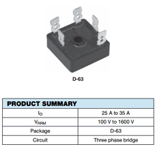
36MT100 datasheet

Description

The 36MT100 is a compact, high-reliability three-phase bridge rectifier rated at 35A average forward current and 1000V reverse voltage. It is designed for efficient AC-to-DC conversion in industrial and instrumentation applications, featuring an electrically insulated case and excellent thermal performance. The device integrates six diodes in a single encapsulated module, simplifying assembly and improving system reliability.

Features

  • Three-phase bridge rectifier module (six-diode configuration)
  • Universal terminals: push-on, wrap-around, or solder
  • Electrically insulated case for simplified mounting
  • High thermal conductivity package
  • Compact size with excellent power-to-volume ratio
  • Center hole for secure mechanical fixing

Absolute Maximum Ratings

Parameter Symbol Value Unit
Average Forward Current IF(AV) 35 A
Peak Repetitive Reverse Voltage VRRM 1000 V
Surge Forward Current IFSM ~300 A
Operating Junction Temperature TJ -40 ~ +150 °C

Typical Circuit Usage

  • Three-phase AC to DC rectification stage
  • Front-end rectifier in motor drives
  • Industrial power supplies
  • Battery charging systems
  • Instrumentation power conversion

How to Choose This Part

  • Select based on required DC load current (≤35A)
  • Ensure voltage rating exceeds peak line voltage with margin
  • Evaluate thermal design for continuous operation
  • Check terminal compatibility with wiring method
  • Compare with higher current modules if load exceeds rating

Applications

  • Motor drives and inverters
  • Industrial SMPS front-end rectifiers
  • Power conversion systems
  • UPS and battery chargers
  • General-purpose three-phase rectification

Alternative / Equivalent Products

  • GBPC35010 – 35A 1000V bridge rectifier (single-phase alternative)
  • VUO35-12NO7 – Three-phase rectifier module
  • MT3510 series – Similar current rating modules
  • SKD 35/12 – SEMIKRON three-phase bridge
  • VS-36MT120 – Higher voltage (1200V) variant

36MT100 Datasheet PDF Download


36MT100 pdf

Other data sheets are available within the file: 26MT10, 26MT100, 26MT120, 26MT140, 26MT160
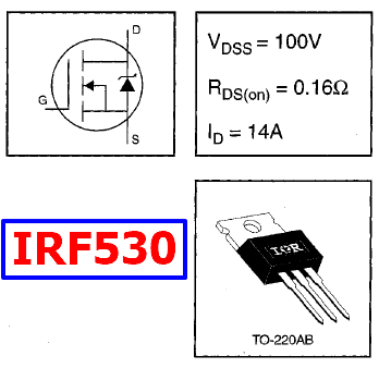
IRF530 Datasheet – 14A, 100V, HEXFET Power MOSFET

What is IRF530?

This is a power MOSFET used in electronic circuits for switching and amplification applications. It is an N-channel MOSFET with a voltage rating of 100V and a current rating of 14A. The IRF530 has a low on-resistance of 0.16 Ohm, which allows it to handle high power and reduce power loss.

Function : 14A, 100V, HEXFET Power MOSFET

Package: TO-220AB Type

Manufacturer: International Rectifier, a semiconductor company that specialized in power management technology, was acquired by Infineon Technologies AG in 2015.

Image and pinout

IRF530 datasheet pinout

Description

This is 100V, 14A, Power MOSFET. Third generation Power MOSFETs from Vishay provide the designer with the best combination of fast switching, ruggedized device design, low on-resistance and cost-effectiveness. The TO-220AB package is universally preferred for all commercial-industrial applications at power dissipation levels to approximately 50 W. The low thermal resistance and low package cost of the TO-220AB contribute to its wide acceptance throughout the industry.

Features of IRF530

1. Dynamic dV/dt Rating

2. Repetitive Avalanche Rated

3. 175 °C Operating Temperature

4. Fast Switching

5. Ease of Paralleling

6. Simple Drive Requirements

7. Compliant to RoHS Directive 2002/95/EC

Advantages

1. It has a low on-resistance, which means it can handle high power and reduce power loss.

2. It has a higher current rating compared to the IRF510, making it suitable for high-power applications.

Disadvantages

1. It has a relatively high gate capacitance, which may limit its use in high-frequency switching applications.

2. It is an N-channel MOSFET, which means it requires a positive gate voltage to turn on, making it incompatible with some circuits that require a negative gate voltage.


Absolute Maximum Ratings (Ta = 25°C)

1. Drain to source voltage: VDSS = 100 V

2. Gate to source voltage: VGSS = ± 20 V

3. Drain current: ID = 14 A

4. Maximum Power Dissipation: Pd = 88 W

5. Channel temperature: Tch = 175 °C

6. Storage temperature: Tstg = -55 to +175 °C


IRF530 Datasheet PDF

IRF540N pdf


Related articles across the web