What is K2611?
It has a maximum voltage rating of 900 volts and a maximum current rating of 9 amperes.
The K2611 is a high voltage, high power MOSFET transistor that is commonly used in power supplies, audio amplifiers, and motor control circuits.
Part Number: 2SK2611
Function: 900V, 9A, N-Channel MOSFET
Package: TO-3P Type
Manufacturer: Toshiba
Image
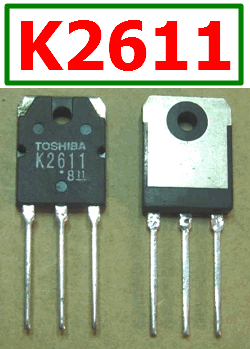
Description
This is 9A, 900V, Silicon N-Channel MOS Type (π−MOSIII) Field Effect Transistor. This parts have high voltage and high power capabilities and low on-resistance for efficient switching. It also ensures fast switching speeds for high-frequency applications.
Features
1. Low drain−source ON resistance : RDS (ON)= 1.1 Ω(typ.)
2. High forward transfer admittance : |Yfs| =7.0 S (typ.)
3. Low leakage current : IDSS= 100 μA (max) (VDS= 720 V)
4. Enhancement−mode : Vth= 2.0~4.0 V (VDS= 10 V, ID= 1 mA)
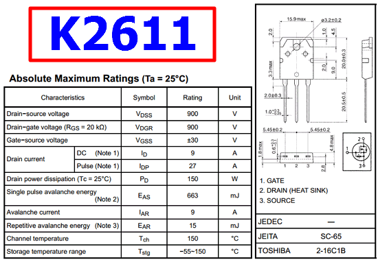
Pinout
Advantages Vs Disadvantages
Advantages:
1. High voltage and power ratings make it suitable for high power applications
2. Low on-resistance results in less power dissipation and higher efficiency
3. Fast switching speed allows for high frequency operation
4. Low gate drive requirements simplify the control circuitry
Disadvantages:
1. The K2611 may be more expensive than lower voltage or lower power MOSFETs due to its high specifications
2. The high voltage rating may require additional safety precautions when working with the device
3. The high power rating may result in the need for additional heat sinking or cooling measures to prevent overheating
Applications:
1. DC-DC Converter, Relay Drive and Motor Drive
FAQs
Q1: What is the difference between a MOSFET transistor and a regular transistor?
A1: A MOSFET transistor operates by controlling the voltage applied to a gate electrode, whereas a regular transistor controls the current flowing through a base electrode. MOSFETs typically have higher input impedance and faster switching speeds than regular transistors.
Q2: How do I protect a MOSFET transistor from overvoltage or overcurrent?
A2: To protect a MOSFET transistor from overvoltage, a voltage clamping device such as a zener diode or TVS diode can be used. To protect against overcurrent, a fuse or current limiting device can be used. Careful consideration of the device’s specifications and the application’s requirements is essential for effective protection.
K2611 Datasheet