This post explains for the IGBT.
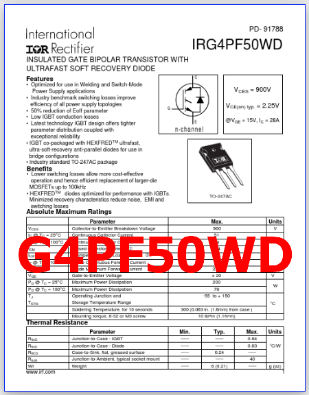
The Full Part Number is G4PF50WD, IRG4PF50WD.
The package is TO-247AC type.
The function of this semiconductor is 900V, 51A, Insulated-Gate Bipolar Transistor.
The manufacturers of this product is International Rectifier.
See the preview image and the PDF file for more information.
Preview images :
1 page
Description
G4PF50WD is 900V, 51A, Insulated-Gate Bipolar Transistor. It is a type of power semiconductor device that combines the advantages of bipolar transistors (high voltage and current handling capability) and field-effect transistors (fast switching and low on-state resistance).
They are also used in applications where high voltage and high current are required, such as in welding equipment and induction heating.
An IGBT consists of a P-N-P-N structure with an insulated gate, which is used to control the flow of current between the emitter and collector terminals. When a positive voltage is applied to the gate terminal, it creates a conducting channel between the emitter and collector, allowing current to flow.
Features
1. Optimized for use in Welding and Switch-Mode Power Supply applications
2. Industry benchmark switching losses improve efficiency of all power supply topologies
3. 50% reduction of Eoff parameter
4. Low IGBT conduction losses
5. Latest technology IGBT design offers tighter parameter distribution coupled with exceptional reliability
6. IGBT co-packaged with HEXFREDTM ultrafast, ultra-soft-recovery anti-parallel diodes for use in bridge configurations
Benefits :
1. Lower switching losses allow more cost-effective operation and hence efficient replacement of larger-die MOSFETs up to 100kHz
2. HEXFREDTM diodes optimized for performance with IGBTs. Minimized recovery characteristics reduce noise, EMI and switching losses

Absolute Maximum Ratings (Ta = 25°C)
1. Collector to emitter voltage: Vces = 900 V
2. Gate to emitter voltage: Vges = ± 20 V
3. Collector current : Ic = 51 A
4. Collector dissipation : Pc = 200 W
5. Junction temperature : Tj = 150 °C
6. Storage temperature: Tstg = -55 to +150 °C
G4PF50WD PDF Datasheet

Posts related to ‘ IGBT ‘
| Part number | Description |
| RJH30E2 | 360V, 30A, IGBT ( PDF ) – Renesas |
| IXGH60N60C3 | 600V, 60A, IGBT, Transistor |
| RJP3053DPP | IGBT, 300V, 30A, Transistor |
| GB6B60KD | 600V, 13A, IGBT, Transistor |
| RJH30H2DPK-M0 | 360V, N-Ch, IGBT |
| 7MBR35SB-120 | 1200V, 35A, IGBT Module |
| 1MBH25-120 | 1200V, 25A, IGBT, Transistor |
| G160N60 | Fairchild, 600V, 160A, IGBT |
| 30J124 | 600V, 200A, IGBT – Toshiba |
| G40N60UFD | G40N60UFD PDF – FGA40N60UFD, 600V, IGBT |

