D2822 PDF Datasheet – Dual Power Amplifier

A dual audio power amplifier typically refers to a device or circuit that amplifies audio signals from two separate sources or channels. This type of amplifier is commonly used in stereo systems, home theaters, and other audio applications where separate audio channels need to be amplified and played through speakers.

Part Number: D2822

Function: Dual Power Amplifier

Package: DIP 8 Pin type

Manufacturer: Shaoxing Silicore

Images:D2822 pdf pinout
Description

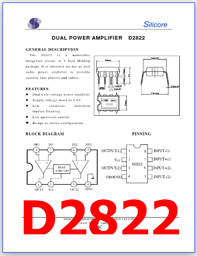
The D2822 is a monolithic integrated circuit in 8 lead Minidip package. It is intended for use as dual audio power amplifier in portable cassette tape players and radios.

1. Stereo Sound: In stereo systems, the left and right audio channels are amplified separately to maintain the spatial audio separation and provide a more immersive listening experience.

2. Speaker Output: The amplified audio signals from each channel are then sent to corresponding speakers. This is important for achieving balanced audio reproduction.

3. Power Output: The power output of each channel indicates how much power the amplifier can deliver to the speakers. It’s typically measured in watts (W) and determines how loud the speakers can play without distortion.

Features

1. Dual Low-voltage power amplifier

2. Supply voltage down to 1.8V

3. Low crossover distortion Outline Drawing

4. Low quiescent current

5. Bridge or stereo configuration
D2822 datasheet amplifier


D2822 PDF Datasheet

D2822 pdf

K20A60U PDF – N-Channel, 600V, 20A, MOSFET, TK20A60U

This is one of the types of MOSFETs and is a kind of transistor.

Part Number: TK20A60U

Marking Number : K20A60U

Function: 600V, 20A, N-Channel MOSFET

Package: TO-220 Type

Manufacturer: Toshiba

Images:

K20A60U transistor mosfet

Description

K20A60U is 600V, 20A, Silicon N Channel MOS Type Transistor(Metal Oxide Semiconductor Field Effect Transistor).

This is a type of field effect transistor (FET) that uses an N-type semiconductor material as the conducting channel to control the flow of current.

Features

1. Low drain-source ON-resistance: RDS (ON) = 0.165 Ω (typ.)

2. High forward transfer admittance: ⎪Yfs⎪ = 12 S (typ.)

3. Low leakage current: IDSS = 100 μA (max) (VDS = 600 V)

4. Enhancement-mode: Vth = 3.0 to 5.0 V (VDS = 10 V, ID = 1 mA)

1 page
mosfet K20A60U pdf datasheet

Absolute Maximum Ratings (Ta = 25°C)

1. Drain to source voltage: VDSS = 600 V

2. Gate to source voltage: VGSS = ± 30 V

3. Drain current: ID = 20 A

4. Drain power dissipation : PD = 45 W

5. Single pulse avalanche energy : Eas = 144 mJ

6. Avalanche curren : Iar = 20 A

7. Repetitive avalanche energy : Ear = 4.5 mJ

8. Channel temperature: Tch = 150 °C

9. Storage temperature: Tstg = -55 to +150 °C


Applications:

1. Switching Regulator


K20A60U PDF Datasheet

Posts related to ‘ 600V ‘

Part number Description
60R580P 600V, N-ch, MOSFET – Magnachip
IN5406 3A, 600V, Silicon Rectifier – Won-Top
GP20B60PD Vces=600V, IGBT – IR
K30T60 600V, 30A, IGBT – IKW30N60T – Infineon
2SK1924 600V, 6A, N-Ch, MOSFET- Sanyo
K13A600 600V, MOSFET (Transistor)
D1650 600V, 3.5A, NPN Transistor
BUH516 1600V, NPN Transistor – ST
N1106 FMN-1106S, 600V, 10A, Diode – Sanken
C5129 C5129 PDF – Vceo=600V, NPN Transistor, 2SC5129 – Toshiba